

Drawings and documents
National Archives restored drawings: drawing
J.J. Adam's Patent Drawing for a Glass Furnace

National Archives, Restored Patent Drawings (Record Group 241) · Full-size scan at the National Archives · Catalog record
Show the text on the drawing Hide (33 words)
Words on the drawing as machine-read by the National Archives; not checked. Useful mainly for searching.
_/__/. Adams, / 7014x / Glass Furnace. / 297 / Patented Apr.21, 1832. / 2985 / N°44 / Reissued Aug- 6, 1842. / Fig:3 / Fig:1. / Rx. / I, / M. / of / help / op
USPTO scan
The patent as scanned by the USPTO
-
 Page 1
-
 Page 2
-
 Page 3


U.S. Patent and Trademark Office · Google Patents
Show the transcription Hide (804 words)
Machine transcription (LightOnOCR) of the pages as scanned by the USPTO, most of them the handwritten copies made when the records were restored after the 1836 fire. Not checked; it can misread handwriting, so compare it with the scan.
Page 1.
7014X
J. J. Adams,
Glass Furnace.
Patented Apr. 21, 1832.

Page 2.
7014Y
April 21, 1832
John J. Adams
Spotters Patent Dated April 21, 1832
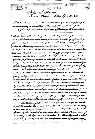
The Schedule referred to in these Letters Patent, and making part of the same, containing a description in the words of the said John J. Adams himself, of his improvement in the process of flattening Window Glass.
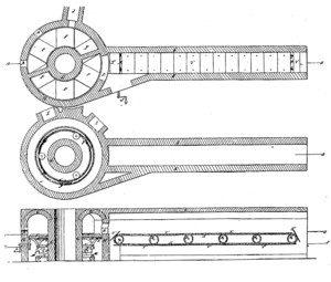
Be it known, that I, John J. Adams, of the City of Washington, and District of Columbia, have made an improvement in the process of flattening Window Glass, which is described as follows: 1. The Wall, including the machine for flattening, made circular, of any convenient size, and is usually built of brick or stone. On the base, and on each side, is an arch to admit fire and fuel. The side or rear hole for admitting the glass cylinders, is left in the wall, near the top, and within about 3 feet of the tempering arch. Two openings for flattening mouths are also left on the same side with the flattening arch, about 5 or 6 feet apart. On the cooling oven side, an opening is left for laying the glass off the flattening stone upon the cooling or tempering plate. 2. An inner circular wall, of about 4 feet diameter is placed on the center of the outer circular wall before described. 3. An arch is sprung, resting on the inner and outer circular walls, leaving a circular opening within the inner circular wall of about 3 feet diameter; this may be either lined of brick or fire clay. This arch is divided into two parts by mantles or divisions, leaving three of the flattening stones, with their intermediate spaces in each apartment. 4. A circular rail way, of about 7 feet diameter, made of cast iron is placed on the center of the before described circular wall, having a groove or flange on it, for admitting a carriage with rollers supporting the flattening apparatus to be next described. 5. The Flattening apparatus, is made of sheet iron, and of a size nearly to fill the circular space included within the circular walls; this may be divided into four or six divisions to receive the flattening stones. The flattening stones with their bases rest on bars or supports placed on a ring and resting on the before mentioned rollers. 6. The cooling arch is about 30 feet long, and 3 feet wide. In one of its chains, about 3 feet apart, are
Page 3.
288 7014Y
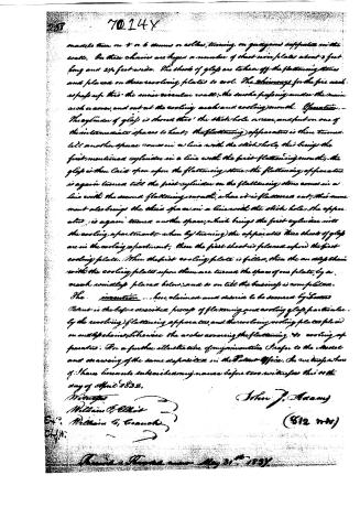
made them on 5 or 6 drums or rollers, turning on grooved surfaces on the walls. On these chains are hung a number of sheet iron plates about 3 feet long and 2½ feet wide. The sheets of glass are taken off the flattening stones and placed on these revolving plates to cool. The shavings for the fire are kept up to the inner circular wall; the smoke passing under the main arch or cover, and out at the cooling arch and cooling mouth. Operation.—The cylinder of glass is shoved into the stick hole or rear, and put on one of the intermediate spaces to heat; the flattening apparatus is then turned till another space comes in a line with the stick hole, this brings the first mentioned cylinder in a line with the first flattening mouth; the glass is then laid upon the flattening stone; the flattening apparatus is again turned till the first cylinder on the flattening stone comes in a line with the second flattening mouth, where it is flattened out; this movement also brings the third space in a line with the stick hole; the apparatus is again turned another space, which brings the first cylinder into the cooling apartments; when by turning the apparatus three sheets of glass are in the cooling apartments, then the first sheet is placed upon the first cooling plate. Then the first cooling plate is filled, then the anvil chain with the cooling plates upon them are turned the space of one plate, by a crank usually placed below; and so on till the business is completed.
The invention... here claimed and desire to be secured by Letters Patent is the before described process of flattening and cooling glass, particularly by the revolving flattening apparatus, and the revolving cooling plates placed on anvil chains, likewise the arches covering the flattening & cooling apparatus. For a further illustration of my invention I refer to the model and drawing of the same deposited in the Patent Office. In witness whereof I have hereunto subscribed my name before two witnesses this 14th day of April 1832.
Witnesses
William G. Elliott
William G. Cranach
John J. Adams
(812 m.v)
Received & Recorded May 31st 1832.
Published accounts: journal notice
Notice in the monthly list of patents, with remarks
Journal of the Franklin Institute, new ser., vol. 10 (1832), p. 245 · View the page
45. For a Process for Flattening Window Glass; John J. Adams, city of Washington, District of Columbia, April 27.
Remarks. The apparatus here patented is intended for flattening cylinder window glass. It consists of a circular oven, or flattening furnace, having in it a circular rail-way of cast iron, upon which the flattening apparatus can be made to revolve. The cylinder is to be put in through the stick hole, and, as it is acted upon by the fuel, is carried round until it arrives opposite to one of the flattening mouths, where it is flattened out upon a stone in the usual manner. By further turning, it is carried round until it arrives at what is called the cooling arch. This is an arch of about thirty feet in length, and three in width; within it two endless chains pass over rollers which cross it at suitable distances, for sustaining the chains. Upon these chains are keyed plates of sheet iron, about three by two and a half feet, upon one of which the flattened plate is laid from the flattening apparatus; the endless chain is then carried forward by turning a winch until another sheet of iron presents itself to receive another plate of glass; the plates are thus gradually carried along the cooling arch, until they are ready to be delivered from the far end. The plan of the cooling arch is similar to that of the annealing ovens at the flint glass works, and would undoubtedly answer the intended purpose; we have not equal confidence in the annealing furnace, and the apparatus within it. Without the aid of actual experiment it is not possible to say that the fire can be so managed as to afford the exact degree of heat which is requisite, or that the revolving rail-way would not be attended by unanticipated difficulties in the course of its operation.
DATAMP: illustration
Illustrations from DATAMP

DATAMP (Directory of American Tool and Machinery Patents), via the Internet Archive · Archived DATAMP page
About this record
- Patentee
- DATAMP
- Date
- the Name and Date index of patents, DATAMP, USPTO records
- Invention
- DATAMP
- Listed in
- the Name and Date index of patents, DATAMP, USPTO records, Jim Shaw's X-patent list, the Journal of the Franklin Institute, Burke's List of Patents (1847)
- The Franklin Institute's journal gives a different date.
- Burke's 1847 Patent Office list gives the same patent.