

Drawings and documents
National Archives restored drawings: drawing
Thomas W. Harvey's Patent Drawing for a Rotary Toggle Joint Press

National Archives, Restored Patent Drawings (Record Group 241) · Full-size scan at the National Archives · Catalog record
Show the text on the drawing Hide (39 words)
Words on the drawing as machine-read by the National Archives; not checked. Useful mainly for searching.
7021X / Class 13, SHEET METAL WARE MAKING. / Stamping. / $10 / Thomas W. Harvey's / Rotary Press. / CLASSIFICATION / Patented Apr, 27,1832. / Patented, 27 / 7021 X / DIVISION. / THE / OIR / Die press.
USPTO scan
The patent as scanned by the USPTO
-
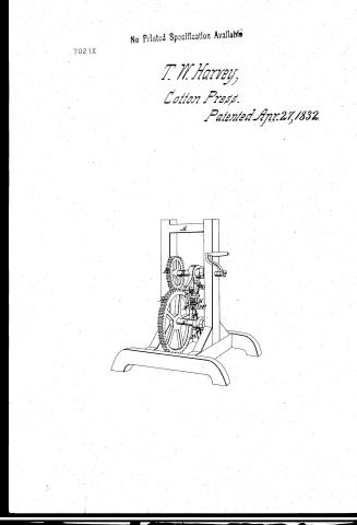 Page 1
-
 Page 2
-
 Page 3
-
 Page 4


U.S. Patent and Trademark Office · Google Patents
Show the transcription Hide (953 words)
Machine transcription (LightOnOCR) of the pages as scanned by the USPTO, most of them the handwritten copies made when the records were restored after the 1836 fire. Not checked; it can misread handwriting, so compare it with the scan.
Page 1.
7021X
No Printed Specification Available
T. W. Harvey,
Cotton Press.
Patented Apr. 27, 1832.

Page 2.
Thomas W. Harvey, Somers, New York.
Sellers Patent (= 7,021 x)
The claims referred to in these Sellers Patent and making part of this specification, a description in the words of the said Thomas W. Harvey having of his improvement being a Rotary Eggbeater.
It is known that Thomas W. Harvey of Somers, Dutchess County, State of New York has made an improvement being a Rotary Eggbeater, which is described as follows:
1. The frame worked A is the common bearing or construction of any convenient size and shape adapted to the machinery intended to be used thereon.
2. The shafts are constructed of sufficient size and strength and placed parallel to each other, turning on bearings or bearings secured to the frame. These shafts are denominated the Clamp Shaft and Sling Shaft. Upon the Clamp Shaft C is a Cog Wheel D of any requisite diameter and number of cogs. Upon the Sling Shaft is placed a Cog Wheel B that works into the aforementioned Cog Wheel and is of half the diameter. Upon the Clamp Shaft are placed a number of Clamps E, properly constructed for the purpose intended in number twice that of the number of Sling Wheels to be denominated into which they are placed for the purpose of being to be made. Upon the Sling Shaft are placed a number of Eggbeater Wheels, which are more than the number of Clamps. The peripheries of the Wheels into which they turn are of equal diameter. The length of the arm of the Eggbeater Wheels from the fulcrum outward is equal to the length of either from the fulcrum to the center of the shaft. The arm from the fulcrum to or joint outward is stretched forward by the application of a spring to either above or below the joint, the joint being governed by a rotating lever. The Slinging from D is placed upon the arm and the arm is enlarged by the action of a second spring E, upon and around the arm and governed by a third spring C, to prevent the same from projecting beyond a given point.
3. The Slinging frame may be placed between said and by the rotating springs impinge on the end of the arm at points of varying sizes, varying in number. The said Slinging frame and arm of arm and similar rotating
Page 3.
the opposite side upon the Clamp Shaft C, thereafter more particularly described in the operation of the Press.
Operation
The material to be struck together can be operated upon as placed by any convenient machinery in the dies attached to either Shaft. The motion being put in motion by the motion of the Cog Wheel D & the arms 22 of the Toggle Links are brought in contact with the Clamp Shaft before they arrive at the parallel line of the centres of the Shafts, this striking force being transmitted by the Spring Springs 20 and the arms being guided forward in a line with the Clamp & the centre of the Clamp Shaft by the operation of the Spring 20 and regulating drum 21 and at a point where the parts meet. The end of the arm 22 is always P on the Clamp and acts as the motion of the outer end and end of the arm by the linear movement of the Clamp Shaft while the accelerating motion (due to line) of the joint Shaft brings up & straightens the Toggle Links at the maximum of force on the parallel line of the centres of the Shafts so that a central impetus is given to the arm upon the centre of the Clamp Shaft during the contact of the parts.
The size of the wheels and their proportions, the diameter of the Clamps, the length of arm, the proportion of speed from Shaft to the other, the number of Toggle Links to the number of Clamps, may all be varied by any known arrangement and proportions retaining however the same principle of action of the Press. The pressure can be given not only directly upon the place at the junction of the two parts as before described but by an application of the force upon a lever upon which the dies may be placed and is also adapted to give motion to a lever distinct from a press.
2. The force may be applied to either Shaft and the Press worked with the Shafts in a perpendicular or horizontal or other position. This Press can be employed for making nuts, rivets, screws, pins, buttons, and so called studs or in any manner and the long or short of size or any other proportions upon all kinds of metal or other materials.
That I claim as my invention is the application of the principle of the lever described, to any Toggle Joint Press, whether the same be made in the form represented in the accompanying drawing or in any other way upon the same principle, it being evident of an indefinite variety of combinations and applications where the lever principle of action is the foundation for doing
Page 4.
7021X
373
petition of James White which is actually called the Eagle Street & State House. The witness being there he was deposed to name the eleventh day of April in the year of our Lord one thousand eight hundred and and thirty two.
Witnesses
Jno B. Branch
Wm P. Elliott
Thomas H. Hersey
1180
Published accounts: journal notice
Notice in the monthly list of patents, with remarks
Journal of the Franklin Institute, new ser., vol. 10 (1832), p. 244 · View the page
42. For a Rotary Toggle Joint Press; Thomas W. Harvey, Jamestown, Chautauqua county, New York, April 27.
Remarks. Without a drawing we shall not attempt a description of this press, particularly as we expect, at an early day, to publish the specification, with an engraving. We will merely observe that what is usually called the toggle joint is not employed in it, the two levers which operate upon this principle not being connected together, although they are brought into contact with each other by the revolution of two parallel shafts from which they project. The machine is about being put into operation in New York, and should it answer the anticipated purpose, it may be applied to the cutting of various articles; to stamping impressions from dies, and for a great variety of other objects.
About this record
- Patentee
- DATAMP
- Date
- the Name and Date index of patents, DATAMP, USPTO records
- Invention
- DATAMP
- Listed in
- the Name and Date index of patents, DATAMP, USPTO records, Jim Shaw's X-patent list, the Journal of the Franklin Institute, Burke's List of Patents (1847)
- Burke's 1847 Patent Office list gives the same patent.