

Drawings and documents
USPTO scan
The patent as scanned by the USPTO
-
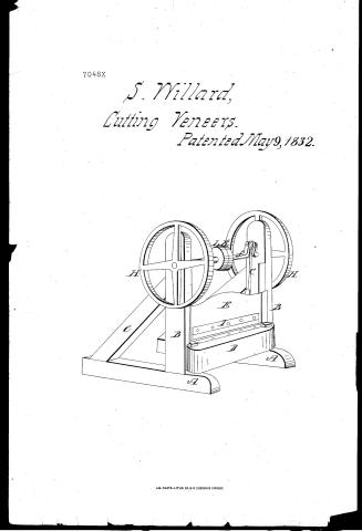 Page 1
-
 Page 2
-
 Page 3
-
 Page 4
-
 Page 5
-
 Page 6
-
 Page 7
-
 Page 8
-
 Page 9


U.S. Patent and Trademark Office · Google Patents
Show the transcription Hide (2,924 words)
Machine transcription (LightOnOCR) of the pages as scanned by the USPTO, most of them the handwritten copies made when the records were restored after the 1836 fire. Not checked; it can misread handwriting, so compare it with the scan.
Page 1.
7048X
S. Willard,
Cutting Veneers.
Patented May 9, 1832.

AM. PHOTO-LITHO. CO. N.Y. (OSBORNE'S PROCESS)
Page 2.
X7048
May 9, 1852
617
Simon Willard of Cincinnati Ohio
Letters Patent
The Schedule referred to in these Letters Patent and making part
of the same containing a description in the words of the said Simon
Willard himself of his improvement in the Board Shearing
machine
To all whom these presents shall come. Be it known that
I Simon Willard of the City of Cincinnati in the County
of Hamilton and State of Ohio, have invented a new and use
ful improvement which consists in the application of the combina
tion of a pair of horizontal shears, with a vibrating cutter and
the requisite machinery as herein after set forth, and applied by
me to the new and useful purpose of cutting boards, planks or
slabs lengthwise, into plasterer's laths, or narrow flooring and other
joiner work, and strips of various lengths and breadths, as may
be required for various other uses, in a manner never in useful
operation before. This application as in the following specification
the same is set forth and constituted a new and useful Board
Shearing machine.
This Board Shearing machine when constructed upon a scale on
ly sufficiently large to cut plasterer's laths four feet in length, one
inch wide, and a fourth thick, with the vibrating cutter calculated
to vibrate in a vertical manner consists of a supporting frame
a driving Shaft, one or two balance wheels and a pair of hor
izontal shears, and other requisite parts as herein after distinct
ly explained viz. The supporting frame is composed of a pair
of sills, about twelve feet in length, five inches thick, and ten
or fifteen wide, framed edgewise on the lower ends of a pair
of upright posts of about the same length and size, and there
in supported by a pair of long braces of the same thickness,
framed edgewise into the sills and posts. The sills of the two
Drawing
Page 3.
triangular side frames are framed four and a half feet apart to the ends of one or two cross rails. A horizontal fixed cutter beam of the same length of the cross rails, about a foot thick is framed into the upright posts with its upper edge about three feet high. Or the frame is the just as may be required to support the operation of the machinery, according to the position the driving shaft is placed in relation to the shears.
In long machines required to cut boards sixteen feet in length a cap beam may be framed within the upper ends of the upright post sufficiently large to support the driving shaft when more than one pair of pitman is required to strengthen the vibrating cutter beam against springing in cutting flooring or other long strips. By means of boxes within which the driving shaft is supported to revolve in the lower end of short projections fastened in the cap beam and extending downwards for that purpose. For machines constructed to cut only four feet laths, the driving shaft is about six feet in length, if made of cast iron the turned bearings are about three inches in diameter, revolving in strong boxes secured to the upper ends of the upright posts. A pair of balance wheels about five or six feet in diameter and weighing about four hundred pounds each, or sufficient to give the required momentum, when making about fifty revolutions a minute, are fastened on the ends of the driving shaft, to revolve either inside or outside of the supporting frames. Or the balance wheel of sufficient weight is fastened on one end of the driving shaft and the driving pulley by the side of a loose pulley on the opposite end is sufficient for short machines.
The fixed cutter of the shears is an iron or nearly a hardened steel bar equal in length to the board the machine is calculated to cut, which may consist of three parts, when room for the gauge carriage is required to advance between them. The upper inside corner of this fixed cutter is an acute angle nicely sharpened and in bevelled and fastened along upon the upper side corner of the fixed cutter beam. When the board is advanced by hand, the fixed cutter
Page 4.
may consist of an entire bar, projecting beyond the cutter beam sufficient for the laths to fall clear. The vibrating cutter constituting the other part of the horizontal shears, may also consist of flats, or be made the whole length of the board it is calculated to cut, it is about four or five inches in width, and about three eighths of an inch thick at the back, so only sufficient to endure the pressure required for cutting the boards, slabs, or planks. The back of this cutter is supported against the shoulder of a square rabbet, made within the front lower corner of the vibrating cutter beam to the front side of which it is nicely bolted edge downwards, and securely fastened by a sufficiency of iron screw bolts with square counter-sunk heads, and located on the side opposite to the fixed cutter.
The vibrating cutter beam is a hard substantial stick of timber, four feet or more in length, and breadth sufficient to prevent it from springing, whose size depends upon the length of boards the machine is calculated to cut. Or the vibrating cutter beam in short machines may consist of a broad cast iron plate with a horizontal flange sufficiently broad to prevent the cutter from springing side ways.
For cutting four feet laths, the vibrating cutter beam is about four and a half feet in length, including at each end a strong wrist or moving joint by which the loose ends of a pair of strong upright pitmans are connected to vibrate by means of iron straps and girths and keys whose upper ends of these short pitmans are connected in a similar manner, to vibrate upon a pair of cranks or counters, from one or two to six or seven inches long according to the length of board it is calculated to cut, and the degree the vibrating cutter is inclined or adjusted, more or less depending in relation to the horizontal fixed cutter, which is required to be about three eighths of an inch to a foot of the length of the cutter, according to the hardness and thickness of the boards, planks, or slabs, it is required to cut. For guiding the vibrating cutter beam on a right vertical line, so that the edges of the two cutters will
Page 5.
625 X7048
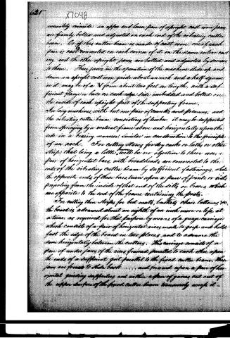
conveniently coincide, an upper and lower pair of upright cast iron jaws, are firmly bolted and adjusted on each end of the vibrating cutter beam. One of these cutter beams is made of cast iron, one of each jaw is cast mounted on each corner of it in the same entire casting, and the other upright jaws are bolted and adjusted by screws to them. These jaws in the operation of the machine slide up and down on upright cast iron guide about an inch and a half square, or it may be of a V form about two feet in length, with a sufficient flange or base on each edge side imbedded and bolted on the inside of each upright post of the supporting frame.
On long machines with but one pair of saws and feeders, and the vibrating cutter beam consisting of timber, it may be supported from springing by a vertical frame above and horizontally upon the side in a bracing manner, similar in construction to the principle of an arch. For cutting slabs for dry casks or laths or other strips that being a little, will be no objection to their use, a pair of horizontal bars, with broadheads are connected to the ends of the vibrating cutter beam by sufficient fastenings, while the opposite ends of these bars, turn upon a pair of joints or rivets projecting from the inside of that end of the dolly or braces, which are opposite to the end of the frame containing the posts.
For cutting thin strips for bed mats, basketry, chair bottoms, &c. the board is advanced about an eighth of an inch more or less, at a time, as required for that purpose by means of a gauge carriage which consists of a pair of horizontal vices made to grip and hold fast the edge of the board in two places, and to advance the same horizontally between the cutters. This carriage consists of a pair of under jaws of the vices framed parallel to each other upon the ends of a sufficient girder parallel to the fixed cutter beam. These jaws are framed to slide back . . . . and forward upon a pair of horizontal guiding supports, and within a pair of grooves cut out of the upper surface of the fixed cutter beam transversely across it.
Page 6.
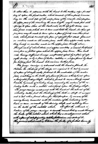
to allow them to advance with the board to the cutter's edge for cutting it upon the fixed cutter, which consists of three parts terminating on the each side of the under jaws of the vice for that purpose. The upper jaws of the vice being the same length, may be made fast with springs to open them at the back ends with upright screws, near their front ends, which are to turn and hold the board. Or these upper jaws may be made to turn upon a pair of joints near their front ends, which joints consists of a pair of upright flat studs formed in mortises made in the under jaws, with their upper ends extending loosely in mortises made in the upper jaws directly above. Through each of which studs and upper mortises a round half-inch iron pin is fitted upon which the upper jaws turn. Their back ends having sufficient leverage are pressed apart by a pair of upright screws, or by a pair of button catches or wedges forced by hand for holding fast the board between iron leathern jaws.
This gauge carriage is advanced with the board or plank, the distance the thickness of the strips are required to be cut by means of a pair of straight racks fastened to the underside of the under jaws matching on the teeth of a pair of pinion wheels fixed upon a horizontal feeding shaft, which is forced to move slowly round beneath, by means of vibrating hands, connecting the motion of the vibrating cutter with a ratchet wheel fixed upon the feeding shaft.
The gauge carriage is advanced with the board at the ascent of the vibrating cutter just the thickness of the cut or strip it is required to cut when forced down for that purpose, by means of the moving hands connected with the motion of the vibrating cutter beam or cam, or crank of the driving shaft, and catching them on the teeth of the ratchet wheel. To effect the alternate motion of the gauge carriage a smooth round hole is made through the hub of the ratchet wheel which has a small grooved wheel with a pair of side projecting catches fastened on one side of it. This grooved wheel moves between the forks of a forked lever, by
Page 7.
which the ratchet wheel and side catches are forced by the tender to slide about one inch back and forward along the feeding shaft. When the board is made fast in the vice, or readiness to be cut into strips, the tender forces by the purchase of the forked lever the side catches of the grooved wheel to catch another similar pair of side propelling catches, made fast to the feeding shaft which thereby advances the gauge carriage until the board is entirely cut into strips, and lifts when a remover fixed upon the advancing gauge carriage arrives for the purpose of unshipping the weighty extremity of the forked lever. The gauge carriage is thereby forced to recede in readiness for another board, by descent of a sufficient weight suspended to raise by a round a broad grooved pulley, fixed upon the feeding shaft as the carriage advances in cutting the next board by means of the side catches forced again to catch as before, and so on alternately it is impelled to vibrate at the pleasure of the tender. This machine is forced into operation by a moving band connecting the motion of the driving pulley (fastened upon the driving shaft) with that of any sufficient power driven while the previously prepared board, plank, or slats not exceeding the length of the cutter is advanced by hand between them against an adjusted gauge, or by the gauge carriage, while the vibrating cutter cuts the narrow flooring upon a level surface, or laths corrugated across it by the next. Or if laths or other narrow strips are cut, they fall directly into a measure, or upon a moving canvas, or ropes impelled round a pair of round shafts forced by their connection by means of bands and pulleys with the driving shaft conveying them to fall into a more convenient measure. Or provided the laths or strips be required to be conveyed in uniform parcels, they are effected by means of a moving band connecting the motion of the grooved sliding wheel with the motion of a pulley reduced to the required slow motion by pulley gearing or worm and toothed wheel, similar to clock work.
Page 8.
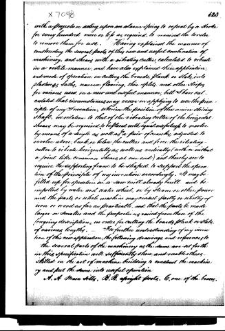
with a projection acting upon an alarm spring to repeat by a stroke for every hundred more or less as required, to remind the tender to remove them for use. Having explained the manner of constructing the several parts of this new and useful combination of machinery, and shears with a vibrating cutter, calculated to vibrate in a rectile manner, and have also explained their application, and mode of operation in cutting the boards, planks or slabs, into plasters, laths, narrow flooring, thin splits, and other strips for various uses, in a new and useful manner, but I have calculated that circumstances may occur in applying to use the principle of my invention, wherein the position of the main driving shaft, in relation to that of the vibrating cutter of the horizontal shears may be required to be placed with equal usefulness to revolve by means of a single as well as a pair of cranks, adjusted to revolve above, back, or below the cutter and force the vibrating cutter to vibrate horizontally as well as vertically (with or without a joint like common shears at one end) and thereby are to require the supporting frame to be shaped, to support the operation of the principle of my invention accordingly. It may be fitted up for operation in a saw mill already built, and be impelled by water and water wheel, or by steam or other power and the parts or whole machine may consist partly or wholly of iron or wood as far as practicable, and that the parts be made larger or smaller and the proportions varied from those of the foregoing description, in order for cutting the boards, planks or slabs, of various lengths. For further understanding of my invention of this new application, the following drawings and references to the several parts of the machinery as the same are set forth in this specification will sufficiently show and enable others skilled in the art of machine building to construct the machinery and put the same into useful operation.
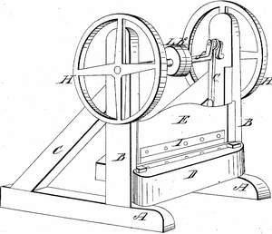
A. A Main shaft. B. B. upright posts. C. one of the beams.
Page 9.
6211 X7048
D. fixed cutter beam. E. vibrating cutter beam, f. driving shears. G. one of the pulleys. H. H. balance wheels. I. the vibrating cutter. K. loose Pulley. L. Driving Pulley, round which the moving band drives the machine into operation.
As my right to the invention of this new and useful board shearing machine, I claim the application of the combination of the machinery, and shears, with the vibrating cutter to a new and useful purpose of cutting boards, planks, or slabs, lengthwise into plasters, laths, narrow flooring and weaving strips, or splints as herein before specified, as represented in the accompanying drawings and as applied by me, in a manner never before useful operation, and claiming only what I have invented new and useful for myself, my heirs, administrators & assigns the full and exclusive right and liberty of making, constructing, using and vending to others to be used, my said new and useful improvement within the United States according to the law for that purpose made and provided.
In testimony that the foregoing is a true specification, and declaration of my lawful claim of said new and useful improvement, I have hereunto subscribed my name, as the inventor of the same, the fourteenth day of September in the year One thousand Eight Hundred and Thirty one.
In the presence of
John Burnham
Albert Kellogg
Simon Willard
(Patented 9th May 1832)
Published accounts: journal notice
Notice in the monthly list of patents, with remarks
Journal of the Franklin Institute, new ser., vol. 10 (1832), p. 324 · View the page
11. For a Board Shearing Machine; Simon Willard, Cincinnati, Ohio, May 9.
Remarks. This machine is intended for cutting laths out of boards, and also for cutting strips and splits for a variety of purposes. Narrow flooring boards, sixteen feet in length, are mentioned as intended to be cut by it. An iron shaft of the required length is to be extended across a strong frame; for laths, this shaft need not, altogether, exceed six feet in length. On its ends there are to be fly wheels, and on its middle a whirl for driving it. Two cranks work a vibrating cutter, or long knife, up and down between cheeks by which it is steadied. The board, or other article to be cut, is to be fed beneath the knife, where it is supported on a fixed beam. The claim is to "the combination of the machinery and shears, with the vibrating cutter, to the new and useful purpose of cutting boards, plank, or slabs, lengthwise, into plasterer's laths, narrow flooring, and weaving strips, or splints." The patentee adds that he claims only what he has invented that is new and useful. It is certainly right for an inventor to claim no more than what is new and useful, but it is for him to tell what he considers to be so; although such a declaration would not be a salvo in case of claiming too much, or include any thing described, that is not claimed.
DATAMP: illustration
Illustrations from DATAMP
DATAMP (Directory of American Tool and Machinery Patents), via the Internet Archive · Archived DATAMP page
About this record
- Patentee
- DATAMP
- Date
- the Name and Date index of patents, DATAMP, USPTO records
- Invention
- DATAMP
- Listed in
- the Name and Date index of patents, DATAMP, USPTO records, Jim Shaw's X-patent list, the Journal of the Franklin Institute, Burke's List of Patents (1847)
- Burke's 1847 Patent Office list gives the same patent.