

Drawings and documents
USPTO scan
The patent as scanned by the USPTO
-
 Page 1
-
 Page 2
-
 Page 3
-
 Page 4
-
 Page 5
-
 Page 6
-
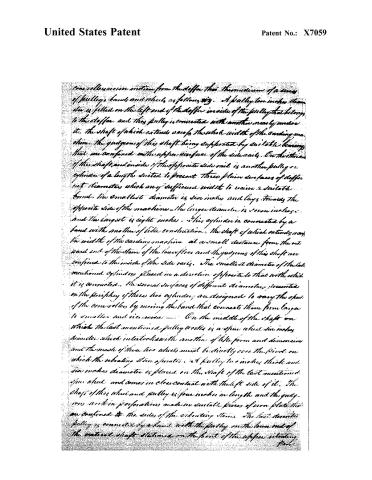 Page 7
-
 Page 8
-
 Page 9


U.S. Patent and Trademark Office · Google Patents
Show the transcription Hide (3,163 words)
Machine transcription (LightOnOCR) of the pages as scanned by the USPTO, most of them the handwritten copies made when the records were restored after the 1836 fire. Not checked; it can misread handwriting, so compare it with the scan.
Page 2.
United States Patent
Patent No.: X7059
Seth Graham
Patent No. X7059
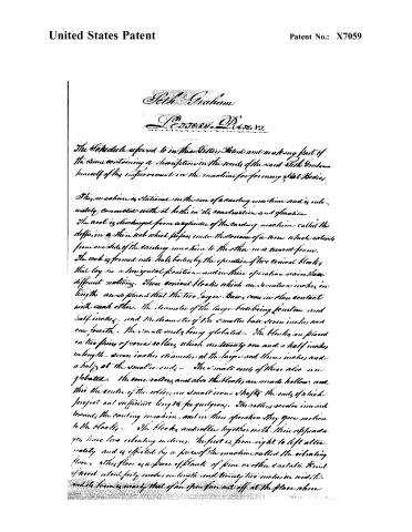
The Certificate referred to in this Letter Patent and making part of the same containing a description in the words of the said Seth Graham himself of his improvement in the machine for forming flat bodies.
This machine is stationary in the sense of a carding machine and is intimately connected with it both in its construction and operation. The wool is discharged from a cylinder of the carding machine, called the doffer, in a thin web which passes under the course of a wire which extends from one side of the carding machine to the other in a curved form. The web is formed into flat bodies by the operation of two conical blocks that lay in a horizontal position and in their operation receive three different motions. These conical blocks which are seventeen inches in length are so placed that the two larger bases come in close contact with each other. The diameter of the larger base being fourteen and half inches, and the diameter of the smaller base seven inches and one fourth. The small ends being globated. The blocks are placed on two pairs of cone rollers, which are twenty one and a half inches in length, seven inches diameter at the large end, three inches and a half at the small ends. The small ends of these also are globated. The cone rollers, and also the blocks, are made hollow, and into the centre of the rollers are small iron shafts the ends of which project out sufficient length for pulleys. The rollers, cones and blocks, move around the carding machine, and in their operation they give motion to the blocks. The blocks and rollers together with their appendages, have two revolving motions. The first is from right to left alternately and is effected by a piece of the machine called the vibrating floor. This floor is a piece of plank of pine or other suitable kind of wood about forty inches in length and twenty two inches in width, and its form is nearly that of an open fan cut off at the place where
Page 3.
United States Patent
Patent No.: X7059
the sticks unite with the ground substituting for the part expunged a stem that is sixty four inches in length and three by two inches square at the extremity out of which and about two inches from the end is a perforation half an inch diameter which works on a pivot that is confined to the floor of the machine building.
The vibrating floor works on a curved railway of sufficient length to accommodate the extent of the motion or vibration — The railway is composed of a curved piece of board about three inches in width and one inch thick confined to the floor of the machine building by my perforations lying with the convex edge towards the vibrating machine. A piece of iron plate one inch in width and three sixteenths of an inch thick is firmly fixed to the convex edge of the curved piece of board. The length of the plate corresponding to the length of the board and the edge of the plate projecting above the surface of the board half an inch. On this projection two friction rollers bear which work in suitable grooves made in the vibrating floor. These friction rollers are three and half inches diameter and half an inch thick with grooves adapted to work on the projection of the railway. The distance from the friction rollers to the outward edge of the floor is five inches and a half and the space between the rollers is twenty six inches and three fourths. The second vibrating motion is effected by another piece of the machine, which is a piece of board in the form of a diamond, four feet in length from one point to the other (the point being rounded a little) and eighteen inches in width called the upper vibrating floor, and the space occupied between the floors is about two inches — The upper floor is supported by a piece of iron plate in the form of an arch which stands upon the lower floor directly over the centre line and two inches from the front side. This arch is confined in its place by seven fastenings and a perforation half inch diameter is made through the upper floor on the centre line at a distance of two inches and a half from the front side and an iron bolt passes through this and a corresponding key perforation made in the top of the iron arch on which the floor rests.
Page 4.
United States Patent
Patent No.: X7059
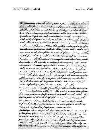
The floor moves upon this belt as upon a pivot. To facilitate the rotation of this floor, a curve railway is fixed on the under surface of the floor with the concave side towards the pivot on which the floor turns. This railway may be of cast iron or other hard metal, eighteen inches in length, one inch and a half in width, and half an inch thick, with a projection rising on the convex side one fourth of an inch. This railway is fitted to operate in grooves made in the circumference of the friction rollers, that are two inches and a half in diameter and half an inch thick. These friction rollers work in grooves made in the lower floor, one inch of clear iron, and three eighths from the centre of the motion to the centre of the grooves in the rollers. All the friction rollers may be made of cast iron or other hard metal. The motions in which the large friction rollers work are covered with wooden caps, which are about four inches long, two inches wide, and one inch thick. To prevent the upper railway from being interfered with its motions by the cap pieces, small grooves are made in the upper surface, corresponding to the rise and motion of the railway. The distance from the centre line on the lower floor to the centre of the grooves in the last mentioned friction rollers respectively is four inches and three eighths.
An arch is erected on the upper floor, the feet of which stand on a centre line drawn lengthwise of the floor. This arch is a curve piece of iron that is an inch and a half in width and half an inch thick. The distance from the floor to the top of the arch is seven inches, and the space occupied between the feet of the arch is about twelve inches. The feet which extend outward two inches are confined to the floor by screws which pass through perforations made in them.
The bearings which sustain the large ends of the cone rollers consist of two pieces of iron each of which is ten inches in length, one inch in width, and half an inch in thickness. In one end of these pieces is an oblong aperture, two inches in length and half an inch in width. These ends are placed one upon another so that they overlap each other three inches, and being thus united, they are placed
Page 5.
United States Patent
Patent No.: X7059
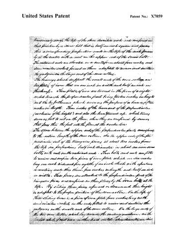
transversely across the top of the above described arch and confined in that position by a screw bolt that is half an inch square and passes into a corresponding perforation made in the top of the arch precisely at the centre with a nut on the upper end of the screw bolt. The extremal ends are elevated in a curved form about four inches and semi-circular sockets formed in them adapted to receive and contain the pulleys on the large end of the cone rollers.
The bearings which support the small ends of the cone rollers are two plates of iron that are one inch in width and half an inch in thickness. These plates of iron are turned in the form of a right-angled triangle the perpendicular part being twelve inches in height and the hypotenuse which answers the purpose of a base is fifteen inches in length. Three inches of the lower end of the perpendicular (exclusive of the height) and also the base turned up, which turns down as far to rest on the floor, when they are confined by screws that pass through the feet into the floor at the centre lines.
The space between the upper ends of the perpendicular parts corresponds to the entire length of the cone rollers. On the upper ends of the perpendiculars and of the triangular pieces at about two inches from the top are perforations half inch diameter in which are iron screw bolts with nuts on the extremal ends. These bolts and nuts are fitted to receive and confine two pieces of iron plate which are six inches long one inch wide and five eighths of an inch thick with apertures or mortices made thereon, four inches in length and half an inch in width. These pieces are attached to the perpendicular parts of the triangular pieces and confined in their places by the iron bolts at the top. By sliding these pieces upward or downward their height is adapted to the proper position of the cone rollers. On the top of these sliding pieces is a piece of iron plate four inches long with semi-circular sockets in the ends fitted to receive and contain the pulleys on the small ends of the cone rollers. On the large ends of the two cone rollers which lay towards the winding machine, are the lines which, if not iron or other hard metal, should have an iron
Page 6.
United States Patent
Patent No.: X7059
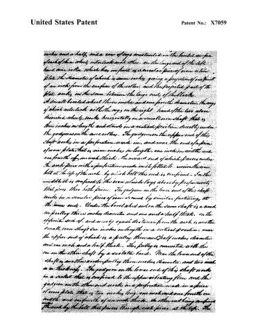
inches and a half, and a row of cogs constructed on the beveled surface of each of these wheels interlock each other. On the large end of the left hand cone roller which lies in front is a circular piece of iron or tin plate. The diameter of which is seven inches, giving a projection of one fourth of an inch from the surface of the roller, and this projected part of the plate works in the seam between the large ends of the blocks. A small beveled wheel three inches and one fourth diameter, the cogs of which interlock with the cogs on the right hand of the two above described wheels, works horizontally on a small iron shaft that is three inches in length and stands in a vertical position directly under the guide on the cone rollers. The guide on the upper end of this shaft works in a perforation made in, and near the end of a piece of iron plate that is nine inches in length, one inch in width and one fourth of an inch thick. The inward end of which passes under the work piece with a perforation made in it fitted to receive the iron bolt at the top of the arch, by which bolt this end is confined. In the middle it is confined to the iron which lays above by properly fitted pins. The guide on the lower end of this shaft works in a similar piece of iron secured by similar fastenings at the inner ends. Under the bevel wheel and on the same shaft is a wood or pulley three inches diameter and one and a half thick. On the opposite side of, and at an equal distance from the arch is another small iron shaft six inches in length in a vertical position near the upper end of which is a pulley three and a half inches diameter and one inch and a half thick. This pulley is connected with the one on the other shaft by a suitable band. Near the lower end of the shaft is another wood pulley three inches diameter and two inches in thickness. The guide on the lower end of this shaft works in a socket that is confined to the upper vibrating floor and the guide on the other end works in a perforation made in a piece of iron plate that is two inches long, one inch and one fourth in width and one fourth of an inch thick, the other end being confined thereto by the bolt that passes through such piece at the top. The
Page 7.
United States Patent
Patent No.: X7059
One roller receives motion from the doffer through the medium of a series of pulleys, bands and wheels, as follows: A pulley ten inches diameter is fitted on the left end of the doffer inside of the pulley that belongs to the doffer, and this pulley is connected with another nearly under it. The shaft of which extends across the whole width of the carding machine, the guidons of this shaft being supported by suitable bearings that are confined on the upper surfaces of the side rails. On the bottom of the shaft and inside of the opposite side rail is another pulley or cylinder of a length suited to present three plain surfaces of different diameters which are of sufficient width to receive a suitable band. The smallest diameter is two inches and lays towards the opposite side of the machine—the larger diameter is seven inches—and the largest is eight inches. This cylinder is connected by a band with another of like construction, the shaft of which extends across the width of the carding machine at a small distance from the cut and end of the stem of the lower floor and the guidons of this shaft are confined to the inside of the side rails. The smallest diameter of the last mentioned cylinder, placed in a direction opposite to that with which it is connected. The several surfaces of different diameters, presented on the periphery of these two cylinders, are designed to vary the speed of the com rollers by moving the band that connects them from larger to smaller and vice versa. On the middle of the shaft on which the last mentioned pulley works is a spur wheel six inches diameter which interlocks with another of like form and dimension and the mesh of these two wheels must be directly over the pivot on which the vibrating stem operates. A pulley two inches thick and six inches diameter is placed on the shaft of the last mentioned spur wheel and comes in close contact with the left side of it. The shaft of this wheel and pulley is four inches in length and the guidons work in perforations made in suitable pieces of iron plate that are confined to the sides of the vibrating stems. The last mentioned pulley is connected by a band with the pulley on the lower end of the vertical shaft situated on the front of the upper vibrating floor.
Page 8.
United States Patent
Patent No.: X7059
and the pulley on the upper end of the shaft being connected with the pulley on the opposite side of the arch as before described completes the series of parts which communicate motion from the doffer to the conveyors.
The lower vibrating floor receives motion from a cylinder of the casing machine called the feeder through the medium of a series of parts. The first of which is a pulley five inches diameter that works on the shaft of the feeder pulley. This pulley is connected by a band with another which works directly under it, and is eight inches diameter. The shaft of the pulley is supported by iron bearings, one of which is confined to the side of the casing machine, and the other is confined to the floor of the machine building. On the same shaft and inside of the pulley last described is another pulley which is three inches diameter and is connected by a band with another twelve inches diameter that works in a horizontal position out side of the casing machine about twenty four inches forward of the rear post. grooves are made in the circumference of these two pulleys fitted to receive the band that operates on them. The horizontal wheel is connected with the vibrating stem by an iron rod or arm with perforations made in it near each end. The perforation in one end works on a pivot inserted in the vibrating stem at the part directly opposite to the center of the horizontal wheel and the perforation on the other end of the arm works on a movable pivot which is placed on the opposite surface of the horizontal wheel at about two inches from the circumference. The movable quality of the pivot on the wheel is designed to vary the extent of vibration so as to correspond with the size of the blocks that are used whether they be large or small. By the operation of the horizontal wheel upon the vibrating stem the lower floor and its dependents are moved alternately from right to left — The second vibrating motion of the upper floor is effected by means of two arms which pass around a pulley three inches diameter that works horizontally on the vibrating stem at a distance of six inches from the floor. One end of each arm is attached to the ends of the upper floor and passing round the pulley to the same side of the casing machine as the upper floor moves
Page 9.
United States Patent
Patent No.: X7059
obliquely to the right or left the end on the opposite end from making a circular motion like the other floor and consequently the cone rolls and blocks are kept in a position parallel to the cylinder from which the web of wool is discharged.
The specific size of the parts of this machine as they are stated in this specification are such as are found to be convenient but they may be varied without impairing the general construction of the machine. To work the machine above described the attendance of two workmen is necessary: one to feed the carding machines, and the other to tend the cone blocks.
The workman receives the web as it is discharged from the doffer and applies the end to the blocks which form it into two flat bodies that are separated by cutting with a pair of shears. Between the large ends of the blocks and while the web is winding round one block the flat body is removed from the other and the block returned to its place in season to receive the web in its return — The machine above described, I claim as the first and sole inventor
Signed:
Wm. J. Graham
Tested:
Wm. J. Graham
J. F. Deane
Henry Craig
3402 w.c.
Published accounts: journal notice
Notice in the monthly list of patents, with remarks
Journal of the Franklin Institute, new ser., vol. 10 (1832), p. 328 · View the page
23. For a Machine for Forming Hat Bodies; Seth Graham, Fayette, Kennebeck county, Maine, May 15.
Remarks. About three years ago, the patents obtained for forming hat bodies were very numerous; and since that time the processes of napping, stiffening, dying, and washing, have been the subject of various application. The forming machinery, for which the patent before us has been granted, does not differ, in the general principle of its action, from several others. The wool is to be delivered from a carding machine in a continued fleece, and received upon two conical formers revolving against a double conical roller, the fleece, or sheet, being cut along the middle as it winds upon the bases of the conical former. To give the required crossing direction to the fibres of the wool, the apparatus carrying the rollers, receives a vibratory motion in a way differing from that in which the same end has been attained in other machines. To describe the mode of doing this would require more space than we can conveniently devote to it. The specification ends with the words, "the machine above described I claim as the first and sole inventor." As most of the parts are used in the same way, and for the same purpose, as in other machines, this claim appears to be rather too broad.
About this record
- Patentee
- DATAMP
- Date
- the Name and Date index of patents, DATAMP, USPTO records
- Invention
- DATAMP
- Listed in
- the Name and Date index of patents, DATAMP, USPTO records, Jim Shaw's X-patent list, the Journal of the Franklin Institute, Burke's List of Patents (1847)
- Burke's 1847 Patent Office list gives the same patent.