

Drawings and documents
USPTO scan
The patent as scanned by the USPTO
-
 Page 1
-
 Page 2
-
 Page 3
-
 Page 4
-
 Page 5


U.S. Patent and Trademark Office · Google Patents
Show the transcription Hide (1,244 words)
Machine transcription (LightOnOCR) of the pages as scanned by the USPTO, most of them the handwritten copies made when the records were restored after the 1836 fire. Not checked; it can misread handwriting, so compare it with the scan.
Page 1.
7066X
No Printed Specification Available
Sheffield & Ingraham.
Paddle Wheel.
Patented May 17, 1832.
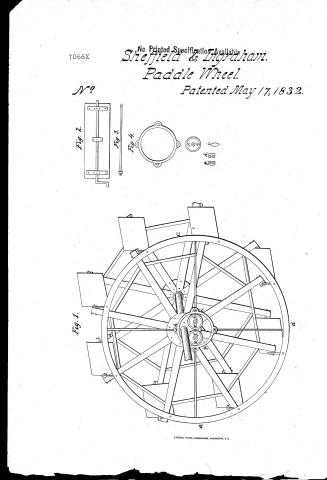
Fig. 1.
Fig. 2.
Fig. 3.
Fig. 4.
Page 2.
John Sheffield & Jonas Ingraham, Citizens of the United States.
Letters Patent Dated May 7th 1832
The Schedule referred to in their Letters Patent, and making part of the same, containing a description in the words of the said John Sheffield and Jonas Ingraham themselves, of their Improvement in the machine for propelling Steam Boats, or other vessels and craft.
To all to whom these presents shall come, John Sheffield and Jonas Ingraham of the County of Erie, State of New York, and Greeting.
Be it known that we, the said John Sheffield and Jonas Ingraham, have invented a new and useful improved wheel or machine, not before known or used in propelling Steam Boats or other vessels and craft, which invention and the manner of using and applying it is as follows.
The Improvement or wheel is constructed or built in the following manner; of suitable size & strength for the boat or vessel it is intended to propel, or for the purpose for which it is intended to be used.
The shaft, arms, flanches, and braces, are made in the same manner as those in wheels in common use. The flanches to be tight on the shaft very true, so that the arms may exactly follow each other, as the wheel revolves, and that the junctions of the brackets may not bind.
The Buckets are made of iron and wood or of iron only, with an iron shaft running through the center, and through the arm of the wheel, forming them, on one end, if only one ring is used, a crank, as Fig. 2, which is inserted in the ring, as in Fig. 4. When two rings are attached to the wheel, then the shaft passing through the center of the bucket and through the arms of the wheel, are to be made forming cranks at...
Page 3.
both the ends, both which cranks are to be inserted into both rings of the wheel in the manner above described. If the power wanted be so great as to require two sets of buckets, then either two or three rings may be attached to the wheel. If two rings only are used, then the second ring is to be attached to the opposite side of the wheel, the shafts of the second set of buckets, being inserted into a second set of arms, and forming cranks, on one end, inserted into the second ring, on the side next the guard of the wheel, in the manner and on the same principle as the buckets are when one ring only is used, as above described.
The third ring may if required be inserted between the two sets of buckets, the shafts of each set then forming cranks at both ends, and the shafts of both sets of buckets are inserted into the centre ring, as above described.
The buckets may be made of iron and wood or cast iron alone, or it may be necessary to make part of the buckets of iron and part of iron and wood, to form counter balances. Those made of cast iron should be cast whole, so that the paddle, shaft and crank shall form but one solid piece, which is the preferable way of constructing them in cases where the weight is wanted to help the centre. Where the buckets are made of iron and wood, one half including the shaft & crank may be of cast iron, and the other part of wood, secured by wrought iron plates, fastened by screw bolts, to the part made of cast iron. When the wheel is required to be light, the buckets should be made of iron and wood, and be fastened to the shaft by screw bolts and plates, in such a manner as not to move or turn upon it. The quaggers of the buckets are to be turned with edgars, so as to prevent the shaft from spreading or drawing in, as the wheel revolves. The Bases, for the guidance of the buckets to run in, are made of two pieces of cast iron or other metal and are fastened into the sides of the arms
Page 4.
of the wheel with two or more screw-bolts.
The shafts of the buckets, are made of equal length and fitted in the boxes of the arms of the wheel, so that the distance from the centre of the box in one arm, to the centre of the box in the opposite and corresponding arm, shall be the same in all the arms, describing equal radii and angles with the periphery of the wheel.
The ring of the wheel, measuring from the centre of the holes therein, receiving the shafts or journals of the buckets, to be made equal in circumference, to a circle described by a line passing through the centre of the boxes in the arms of the wheel, and its diameter equal to the distance from the centre of the box in one arm, to the centre of the box in the opposite and corresponding arm. And the holes in the ring, to receive the shafts or journals of the buckets, to be made in right lines with the perpendicular line of the wheel, corresponding exactly with the holes in the arms, so that the radian angles described by both the ring and arms of the wheel, shall be equal, each revolving on its own centre.
A smaller ring (Fig. 1, h, k, l) is made to keep the larger in its proper place, and placed in the centre of the larger one, its diameter measured on the inside, to be twice the length of the arm of a bucket, added to the diameter of the main shaft of the wheel; fastened to the centre of the larger ring by four iron rods, with nuts, and revolving around two friction rollers (Fig. 1, c, f,) the rollers being fastened to the outside the boat or vessel, by two large bolts. If the wheel be constructed with two large rings, then there must be two additional friction rollers, fastened to the guard of the boat or vessel to keep the second or outer ring in its place. The Petitioner only claim as their Invention, the main or larger Ring, the central ring, friction rollers, & iron rods attached to the rings, by means of which the buckets are kept in a perpendicular position. This wheel
Page 5.
may be used and applied for the propelling of Steam Boats and other vessels and water craft, as the common wheels, for such purpose, now in use are.
References.
Fig. 1. Is a view of the Wheel.
a, b, c, d, Main or Larger Ring
e, f, g, Central Ring,
i, j, Friction Rollers.
Fig. 2. Bracket. Fig. 3. Stone Rod, Fig. 4. Central Ring.
e, f, Friction Rollers g, h, Boxes. i, Section of main Ring cut at b, d. Fig. 1.
In witness whereof we have hereunto set & subscribed our names this twentieth day of December in the year of our Lord one thousand eight hundred and thirty one.
Witnesses.
Antreas Thompson junr.
Henry Crawford
John Sheffeldy
Jonas Ingraham
(1215 words)
Epa
NGL
Drawing
Published accounts: journal notice
Notice in the monthly list of patents, with remarks
Journal of the Franklin Institute, new ser., vol. 10 (1832), p. 329 · View the page
28. For an improvement in the Paddle Wheel for steam boats, &c.; John Sheffield and Jonas Ingraham, Buffalo, Erie county, New York, May 17.
Remarks. We see not the slightest variation in principle, and very little in arrangement, between this paddle wheel and such as have been repeatedly proposed, patented, and essayed, both here and in Europe. The object is to preserve the paddles in a vertical position, and the means of effecting this is the employment of a wheel eccentric to the shaft of the paddle wheel, pins, or cranks, from which act upon the buckets, that are connected also to the rim of the main wheel. The specification describes the whole very clearly, without, however, taking the slightest notice of the fact that similar wheels have been heretofore made, or furnishing any thing in the form of a claim. A person ignorant upon the subject, and reading this specification, would at once conclude that the whole thing was a new contribution from the arcanum of mechanical science. Such wheels, however, have had fair and long continued trials, but have not been found in any respect superior to the common paddle wheel, whilst they are much more expensive, increase the friction greatly, and, from their complexity, are very liable to derangement.
About this record
- Patentee
- DATAMP
- Date
- the Name and Date index of patents, DATAMP, USPTO records
- Invention
- DATAMP
- Listed in
- the Name and Date index of patents, DATAMP, USPTO records, Jim Shaw's X-patent list, the Journal of the Franklin Institute, Burke's List of Patents (1847)
- Burke's 1847 Patent Office list gives the same patent.