

Drawings and documents
USPTO scan
The patent as scanned by the USPTO
-
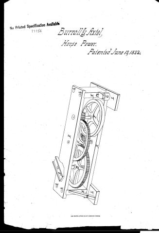 Page 1
-
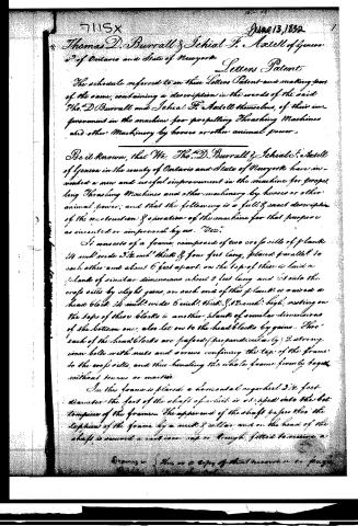 Page 2
-
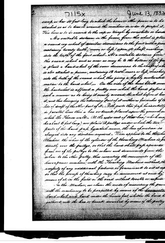 Page 3
-
 Page 4


U.S. Patent and Trademark Office · Google Patents
Show the transcription Hide (911 words)
Machine transcription (LightOnOCR) of the pages as scanned by the USPTO, most of them the handwritten copies made when the records were restored after the 1836 fire. Not checked; it can misread handwriting, so compare it with the scan.
Page 1.
No Printed Specification Available
7115X
Burrall & Axtel,
Horse Power.
Patented June 13, 1832.

AM. PHOTO-LITHO. CO. N.Y. (OSBORNE'S PROCESS)
Page 2.
7115x
June 13, 1832
Thomas D. Burrall & Ichial F. Astell of Geneva Co. of Ontario and State of New York
Letters Patent
The schedule referred to in these Letters Patent and making part of the same, containing a description in the words of the said Tho. D. Burrall and Ichial F. Astell themselves, of their improvement in the machine for propelling Thrashing Machines and other Machinery by horses or other animal power,
Be it known, that We, Tho. D. Burrall & Ichial F. Astell of Geneva in the county of Ontario and State of New York have invented a new and useful improvement in the machine for propelling Thrashing Machines and other machinery by horses or other animal power; and that the following is a full & exact description of the construction & operation of the machine for that purpose as invented or improved by us. "We":
It consists of a frame, composed of two cross sills of plank 14 inch wide 2 1/2 inch thick & four feet long, placed parallel to each other and about 6 feet apart; on the top of these is laid a plank of similar dimensions about 8 feet long and set into the cross sills by slight gains, on each end of this plank is raised a head block 14 inch wide 6 inch thick & 12 inch high, resting on the tops of these blocks is another plank of similar dimensions of the bottom one; also let on to the head blocks by gains. Thru' each of the head blocks are passed (perpendicularly) 2 strong iron bolts with nuts and screws confining the top of the frame to the cross sills, and thus binding the whole frame firmly together without tenons or mortise.
In this frame is placed a horizontal cogwheel 3 1/2 feet diameter the foot of the shaft of which is eclipsed into the bottom piece of the frame. The upper end of the shaft passes thru' the top piece of the frame by a nut & collar, and on the head of the shaft is mounted a cast iron cap or trough, fitted to receive a
Drawings &c. Here is a copy of that annexed on page 2.
Page 3.
June 13, 1832
sweep or bar 10 feet long to which the horse or other power is to be attached so as to travel around the machine in order to propel it. This lever is to be secured to the saw or trough by screws or bands.
At a suitable distance in the frame, from this wheel is placed a second cog wheel of similar dimensions to the first with a pinion containing twenty teeth (more or less) upon its shaft, meshing into the teeth of the first wheel. At a suitable distance from this second wheel and as near as may be to the bottom of the frame is placed a band wheel of the same dimensions to the shaft of which is also attached a pinion, containing 12 teeth (more or less), meshing into the teeth of the second wheel, thus giving a highly accelerated motion to the band wheel. On the side of the head block near the band wheel is affixed a pulley over which the band passes in such a manner as to bring it nearly around the wheel before it leaves it, and thus bringing the returning part of it within a few inches of the line of draft of the other part of it. Both parts then pass horizontally in parallel lines thru a box or trough placed upon the ground, on which the horses walk. At the outer end of this box (which may be about 6 feet long) are placed 2 pulleys under which the two parts of the band pass, by which means, the line of motion is changed into any direction required. When applied to the threshing Machine, the wheel of the cylinder of the threshing Machine is placed directly over the pulleys, so that the band shall pass upwards from one of the pulleys to the wheel and downwards from the wheel to the other pulley, thus connecting the movements of the horse power machine with the Threshing Machine without the necessity of any additional fixtures or framework to set it up so that the process of threshing may be commenced at once by means of it, in the field or the road without trouble or expense.
In this Machine, we claim the mode of connecting the frame with the machinery to be propelled by means of the horse wheel and band under the horse feet whether the band be gathered into the box or trough assembled by means of the pulley.
Page 4.
7115x
June 13, 1832
or passed under foot by two hands or otherwise—and we also claim the peculiarly simple, strong and useful construction & combination of the frame of the horse power Machine as described above. In Testimony whereof that the above is a true specification of our said improvement as above described we have hereunto set our hands and seals this 20th day of March 1832.
Witnesses
Eurolas Hastings
James Wm Handfield
Thos D Burrall
Jehial F Atzell
(Patented June 13, 1832.)
Published accounts: journal notice
Notice in the monthly list of patents, with remarks
Journal of the Franklin Institute, new ser., vol. 11 (1833), p. 25 · View the page
20. For a Machine for Propelling Thrashing Machines and other machinery, by horses or other animal power; Thomas D. Burrall, and Jehiel F. Axtell, Geneva, Ontario county, New York, June 13.
Remarks. This machine for propelling machinery which is itself to be propelled by horse power, is to have a sweep ten feet long, to which the horse is to be geared; on the shaft is a cog wheel to drive a pinion on another shaft, which also has a cog wheel taking into a pinion on a band wheel shaft. These various gearings are to give great velocity, and are well contrived to consume a large portion of power by friction. Among the other grand improvements claimed is "the peculiarly simple, strong, and useful construction and combination of the frame of the horse power machine," which is constructed exactly like a thousand other frames.
DATAMP: illustration
Illustrations from DATAMP
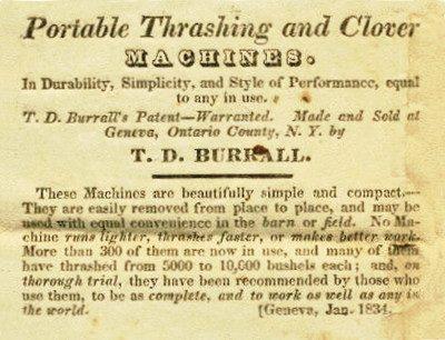
DATAMP (Directory of American Tool and Machinery Patents), via the Internet Archive · Archived DATAMP page
About this record
- Patentee
- DATAMP
- Date
- the Name and Date index of patents, DATAMP, USPTO records
- Invention
- DATAMP
- Listed in
- the Name and Date index of patents, DATAMP, USPTO records, Jim Shaw's X-patent list, the Journal of the Franklin Institute, Burke's List of Patents (1847)
- Burke's 1847 Patent Office list gives the same patent.