

Drawings and documents
National Archives restored drawings: drawing
John J. How's Patent Drawing for a Pin Machine


National Archives, Restored Patent Drawings (Record Group 241) · Full-size scan at the National Archives · Catalog record
Show the text on the drawing Hide (128 words)
Words on the drawing as machine-read by the National Archives; not checked. Useful mainly for searching.
Sheet 1. 85. METAL WORKING, / S. / Pins, Making / JOHN U. HOW'S / 3 freels that 1 / our isluication / PIN MACHINE / 7/23-X / Patented 22 June 1832.X June / Fig.1. / www / y/o
Sheet 2. John J Hon Hoo / 3 theets / Pan Mashine / Rigo3 / Fig. 2. / Patented 22 Jane 1832 / 7123-+ / 71 / 3-+ / 26 / A' / 122 A / 10 / 22 / of / Fig.5, / as / 24 / Fig.4. / 14 / it / 25 / 43 / Emo / 23'
Sheet 3. E. / Figgy / yy / Pin Machine / Patented June 1832 / Sheet / 7123.+ 71 2 3. +. / Fig.8. / OF / 010 / 10 / 10 / ZD / OF / 6' / 18 / 19 / Fig.7. / 16 / Fig. 6 / De / in / mmm / Dig / of
Sheet 4. 7123-X / Sheet 1-2,Sheets. / J.J.How J. / Pin Machine, / Patented June 22, 1832. / Fig.1 / Fig.8 / Fig.9 / E' / Fig.6 / Fig.7 / 10 / 19 / 16 / I' / Da / Lawrence / RAB
Sheet 5. 7123-X / Sheet 2-2 Sheets. / JJ. How, / Pin Machine, / Patented June 22, 1832. / Fig. 2 / Fig, / 26=[ / G 7 / 22 / 10 / X- / Fig.4 / Fig.5 5 / A' / 22 / 26. / 14 / Ds / 14' / 25 / 13 / 25' / /3 / 23 / OF / 23' / 00000000 / RAB Lawrence
USPTO scan
The patent as scanned by the USPTO
-
 Page 1
-
 Page 2
-
 Page 3
-
 Page 4
-
 Page 5
-
 Page 6
-
 Page 7
-
 Page 8
-
 Page 9
-
 Page 10
-
 Page 11


U.S. Patent and Trademark Office · Google Patents
Show the transcription Hide (2,888 words)
Machine transcription (LightOnOCR) of the pages as scanned by the USPTO, most of them the handwritten copies made when the records were restored after the 1836 fire. Not checked; it can misread handwriting, so compare it with the scan.
Page 1.
7123X
3 Sheets—Sheet 1.
J. J. HOW.
PIN MACHINE.
Patented June 22, 1832.
Fig. 1.
![Diagram of a pin machine with labeled parts including g, w, c, r, e, c, t, d, j, q, h, o, k, l, m, n, p, f, b, a, and others.]
Page 2.
7123X
3 Sheets—Sheet 2.
J. J. HOW.
PIN MACHINE.
Patented June 22, 1832.
Fig. 3.
Fig. 2.
Fig. 5.
Fig. 4.
Page 3.
7123X
J. J. HOW.
PIN MACHINE.
Patented June 22, 1832.
3 Sheets—Sheet 3.
Fig. 1.
Fig. 8.
Fig. 9.
Fig. 6.
Page 4.
7123 X
John Howe
Letters Patent
The article referred to in these Letters Patent and making part of the same containing a description in the words of the said John Howe himself of his improvement in the machine for manufacturing pins.
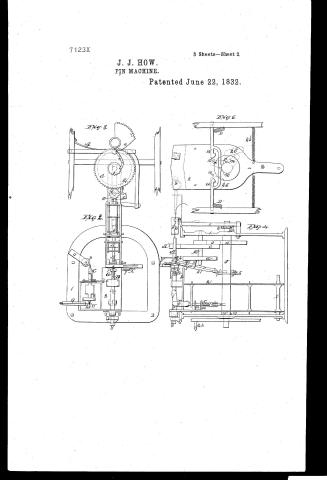
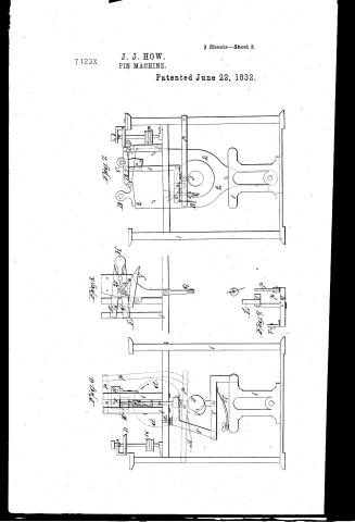
To all whom it may concern. Be it known that I John S. Howe have invented an improved machine for manufacturing common pins by means of which, the wire is straightened, cut into lengths, headed and pointed, and the pin delivered in a state ready for whitening; and that the following is a full and exact description thereof, and of the manner in which it operates, reference being had to the accompanying drawings, which make a part of this specification. Fig 1. is a perspective view of the machine. Fig 2. A plan showing the principle working parts. Fig 3. a section showing the action for winding the head and cutting off the wires &c. Fig 4. a section parallel to the main shaft, showing some of the necessary parts of the machine. Fig 5. end elevation of the movable frame, or carriage. Fig 6 vertical section at right angles to the main shaft, with the feeding apparatus &c. Fig 7. section in the same direction, showing the means of opening the printing forceps and other parts. Fig 8 the feeding vice and its appendages. Fig 9. apparatus concerned in closing the printing forceps. Fig 7. &c.
The individual parts of the machine are marked in the respective figures with Roman Capitals with small roman letters with static capitals, and with numbers. The same marks on the different figures refer in all cases to similar parts.
A Head winding apparatus. B. Head compression. C. Printing forceps. D. Printing wheel. E. Feeding vice. N. Union on the wind and tool.
a. An eccentric curve, combined with a segment having 14th or 15th which together extend over one half of the circumference of the main shaft, and act during one half its revolution upon —
Page 5.
580 X7123 2
b an example connected with a pinion which is driven through a common revolution by the action of a at each revolution of the main shaft.
The curves, a b, are each involute, evolved from a circle having for its radius half the distance between the shafts marked a b K. each of them extends over one quarter of a circle, and from a circle corresponding with the pitch line of the pinion b, to one corresponding with that of the action of a on b. In operation they act and react upon each other at the line of centers. This being a new and peculiar mode of effecting the kind of motion required, I have noted it at greater extent than most other parts of the machine, which, although new in their combination, are not considered as such in this particular action. C Wheel, driving the pinion A' they being to each other as 1 to 4. d, a wheel or washer having on its periphery a gear tooth and a "micrometer notch" which during when the system of levers p, governs the movements of the blade 101 c.f.g.h.i. Band wheels, communicating motion from the main shaft to the pointing, forester, and feeding wheels.
k. a wheel acting on lever o carrying back the feeder 3 which exhibits the main view of a trough wheel by the spring 15
L. Wheel acting upon a system of levers, carrying back the heading wire feeder, which is brought up by a spring 15'
m.m' Arms with friction rollers at their ends, and acting on cams, which serve to move the carriage 2 back and forth.
N. Wheel giving action to the head compressing apparatus.
o. Lever acting on the feeder 3' p. (see referred to in a)
q. Lever, which by the action of p, operates on 3 a bent lever which keeps open the pointing forester during the required period.
r. Lever 3 carrying back the heading wire feeder 3'
t. Head compressor levers. s. Standard on frame 11 for the regulating screw 8' w a wing regulating the position of the pointing forester previous to their being opened
X arm connected with a double lever (20) acting between the jaws of the heading vice 21, and opening them when required.
Page 6.
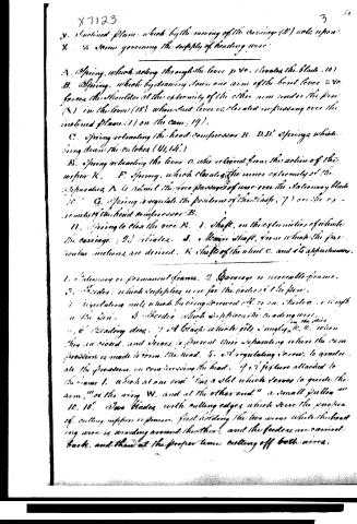
Y. Inclined plane, which by the moving of the carriage (2) acts upon X, a screw governing the supply of heading wire.
A. Spring, which acting through the lever p v c, elevates the blade (10).
B. Spring, which by drawing down one arm of the bent lever s v c, forces the shoulder at the extremity of the other arm under the pin (N) in the lever (18) when said lever is elevated in passing over the inclined plane (1) on the cam (19).
C. Spring retracting the head compressor B.
D, D'. Springs which bring down the rollers (U, U').
E. Spring retracting the lever O, who is raised from the action of the wrist K.
F. Spring, which elevates the inner extremity of the apparatus A to admit the free passage of wire over the stationary blade (10).
G. Spring to regulate the position of the blade (7) on the extremity of the head compressor B.
H. Spring to close the vice H.
I. Shaft, on the extremities of which the carriage (2) operates.
J. A main shaft, from which the particular motions are derived.
K. Shaft of the wheel C, and its apparatus.
1. Stationary or permanent frame.
2. Carriage or movable frame.
3. Feeders, which supplies wire for the bodies of the pins.
4. Regulating nut, which by being screwed off or on, shortens or lengthens the pin.
5. Sheeters, which supplies the heading wire.
6, 6'. Heading dies.
7. A blade which fits snugly on the dies when in closed, and serves to prevent their separating when the compression is made to form the head.
8. A regulating screw, to gradually alter the pressure in compressing the head.
9. A fixture attached to the frame 1, which at one end has a slot which serves to guide the arm, of the wing W, and at the other end a small pull.
10, 10'. Two blades, with cutting edges, which serve the purpose of cutting nippers or pins, and holding the two wires while the heading wire is winding around the other, and the feeders are carried back, and then at the proper time cutting off both wires.
Page 7.
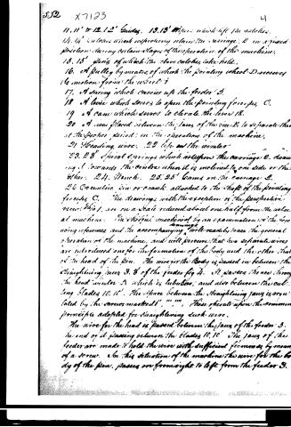
11, 11' & 12, 12' Guides. 13, 13' Wipers which lift the catches.
14, 14' Catches which respectively retain the carriage 2 in a fixed position during certain stages of the operation of the machine.
15, 15' Jaws of which the above catches take hold.
16. A pulley by means of which the pointing wheel D receives its motion from the wheel 1.
17. A spring which carries up the feeder 3.
18. A lever which serves to open the pointing forceps C.
19. A cam which serves to elevate the lever 18.
20. A wire placed between the jaws of the vice 2 to separate them at the proper period in the operation of the machine.
21. Heading wire. 22. Left on the winder.
23, 23' Spiral springs which act upon the carriage 2, drawing it towards the centre when it is inclined to one side or the other. 24. Bench. 25, 25' Gears on the carriage 2.
26. Eccentric pin or crank attached to the shaft of the pointing forceps C.
The drawings, with the exception of the perspective view Fig 1, are on a scale reduced about one half from the actual machine. The skilful mechanic by an examination of the foregoing references and the accompanying drawings will readily trace the general operation of the machine, and will perceive that two separate wires are introduced, one for the formation of the body and the other that of the head of the pin. The wire for the body is passed in between the straightening jaws 3, 3' of the feeder Fig 4. It passes thence through the head winder A which is tubular, and also between the cutting blades 10, 10'. The space between the straightening jaws is regulated by the screws marked 1", 1", 1". These operate upon the common principle adopted for straightening such wires.
The wire for the head is passed between the jaws of the feeder 3. The end of it passing between the blades 10, 10'. The jaws of the feeder are made to hold the wire with sufficient firmness by means of a screw. In this situation of the machine the wire for the body of the pin, passes on from right to left from the feeder 3.
Page 8.
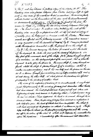
to No 7, and lies between the cutting edges of the blades 10, 10'. The heading wire also passes between these blades, but from left to right and in this case if the machine be set in motion, the various parts which concur in the formation of the pin will be simultaneously or successively acted upon. In forming the head of the pin, the movable blade 10, with half its close on the fixed blade 10', holding the two wires firmly between their edges. The head winder A will at once, catching the end of the heading wire in a lip or projection &c. at its end and winding it spirally upon the body wire in contact with the blades. These movements are effected in the following manner. The eccentric curve or wing connected with the segment of cone a (fig 3.) comes in contact with the eccentric connected with the pinion b on the shaft K (fig 3.) the former carrying the latter forward until the tooth of the segment a strikes into gear with the leaves of the pinion b. In this part of the movement, each of the shafts J & K passes through one fourth of a revolution; in the subsequent part of the movement, that is when the segment a acts upon the pinion b, the main shaft J passes through one fourth whilst the shaft K passes through 3/4 of a revolution: so that K makes one entire revolution and J but one half, and the pinion on the winder A is driven through four revolutions during half a revolution of J and is at rest during the other half, at which period the operations are effected preparatory to the winding of another head.
As some of the respective operations go on simultaneously, it may be supposed that previously to the winding process just described, other heads had been wound, the head perfected and the pin cut off and taken into the pointing screws, and carried to the pointing wheel, I shall however carry the one on which I have supposed the head to be wound, through its several stages. When the pointing screws have arrived in a position to take hold of a pin, the head of which had been completed, the wheel d, will have arrived at the position in which it is shown in fig 6. The forces will then be closed on the pin previously projected, and the wires cut off by the action of the wheel d, which will depress the movable head upon the fixed one. Immediately after the movement last described,
Page 9.
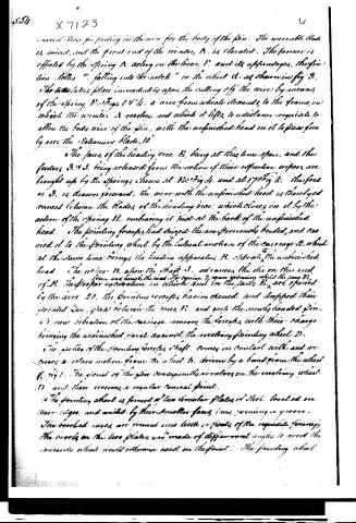
moved those for feeding in the wire for the body of the pin. The movable blade is raised, and the front end of the window, A, is elevated. The former is effected by the spring A, acting on the lever, P, and its appendages, the friction letter "r" falling into the notch "n" in the wheel C, as shown in fig 3. The latter takes place immediately upon the rolling off the wire by means of the spring P. Figs 1 & 4. a wire from which descends to the frame in which the window A revolves, and which it lifts to a distance requisite to allow the body wire of the pin, with the unfinished head on it to pass freely over the stationary blade. 10'
The jaws of the heading vice B, being at this time open, and the feeders 3, 4, 5, being released from the action of their respective wipers, are brought up by the springs shown at E in Fig 4, and at 17 in Fig 6. The feeder 3, is drawn forward, the wire with the unfinished head is thereby advanced between the blades of the heading vice, which closes on it by the action of the spring H, embracing it just at the back of the unfinished head. The pointing forceps had seized the one previously headed, and carried it to the pointing wheel, by the lateral motion of the carriage 2, which at the same time brings the heading apparatus, B, opposite the unfinished head. The wiper N, when the shaft J, advances, the die on the end of B, turns and crushes the head. The carriage 2, again returning whilst the jaws B, in the proper elevation in which and in the jaws B, are opened by the lever 21, the pointing forceps, having opened and dropped their pointed pin, pass between the jaws B, and pick the newly headed pin. A new vibration of the carriage removes the forceps with their charge, bringing the unfinished point against the revolving pointing wheel D. The pulley of the pointing forceps shaft, comes in contact with and receives a rotary motion from the wheel b, driven by a band from the wheel C, fig 1. The point of the pin consequently revolves on the revolving wheel D, and there receives a regular conical point.
The pointing wheel is formed of two circular plates of steel, bevelled on their edges, and united by their smaller faces, thus forming a groove. The bevelled edges are formed with teeth or points of the requisite fineness. The bevels on the two plates may be made of different angles to avoid the concavity which would otherwise exist on the point. The pointing wheel
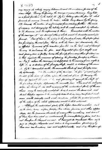
Page 10.
may vary in its velocity, ranging between 50 and 100 revolutions for one of the main shaft. During the pointing the carriage remains stationary, being held in a fixed position by the catch 14. (fig 5.) holding upon the pin 15. which prevents its moving towards the centre, whilst being drawn by the spring 23. towards the centre, it is prevented from receding farther. The mode of engaging and disengaging the catches will be made manifest by attention to the drawings, and the references to them. Connected with the motion of the carriage (2) are several others which must be simultaneously performed. One of these is, the giving to the pointing forceps, the proper position for seizing the next pin, that is, with its lower jaw downwards. This is effected by means of the eccentric pin 26. on the back end of the shaft the ring W. embracing this pin, and being acted upon by a weight and cord passing over a pulley turns the forceps from any other position into that required; the manner of opening the pointing forceps is shown in Fig 7. where the carriage is supposed to be moving from right to left. C. is a section of the forceps shaft, and S. a section of the arm (1. fig 2) connected with the moveable blade of said forceps near its extremity. In the motion of the carriage, the pin "projecting from the side of the lever 18. slides upon the inclined plane 19 carrying the lever up against the arm 21, and pressing it against the shaft of the pointing forceps, depresses the moveable jaw 20th, and the subsequent action of closing it, as well as many of the individual parts of the machine, may be variously modified so as to answer the same end, and do not therefore require to be minutely described, as every competent workman would actually make such variations, whilst the general principle of the action of the whole apparatus would be still retained.
Although the individual parts of the before described machine, such as the levers, cams, wings, forceps, dies, wheels, pins, and other appendages, are the common elements of many other machines, and several of them have been used as instruments for manufacturing pins, and cannot therefore be claimed as new. I have yet to combine them as to give a specific character and action to my machine, producing by these new combinations, new and useful results, and it is therefore up
Page 11.
556 X7123 46
in this combination of parts, that I mainly rest my claim to its exclusive use, and, besides this general arrangement, I claim the specific arrangement of the apparatus, by which the winding of the wire to form the head of the pin, is effected, and I also claim the peculiar arrangement of the eccentric curves and segments, represented in Figure 6, the main acting parts of which are marked a, b, b, which arrangement produces a rotary motion varying in its velocity, and which may be advantageously applied in the construction of other machinery where such a motion must be advantageous. Such application however to any machine will... be considered as a violation of my right.
Witnesses
John O. Howe
( Patented 22. June 1882 )
Published accounts: journal notice
Notice in the monthly list of patents, with remarks
Journal of the Franklin Institute, new ser., vol. 11 (1833), p. 28 · View the page
30. For a Machine for manufacturing pins; John J. Howe, North Salem, West Chester county, New York, June 22.
Remarks. In the ordinary mode of manufacturing pins, the wire is first straightened in considerable lengths, these wires are then cut, a number at a time, into lengths of six or eight inches; the next operation consists in pointing these wires at both ends, which is also effected a number at a time; as many of the wires as can be conveniently laid upon the index finger, be held down in a row, and rolled over by the action of the thumb, are brought into contact with stones, or file cut disks of steel, in rapid motion, and thus pointed, the same operation being performed on each end. The length of a pin is then cut off by an apparatus again operating on a considerable number, and the pointing and cutting are thus repeated until the whole wire has been used. The operation of heading is performed upon each pin singly; the twisted wire is slipped over the pin, and receives three or four blows in the heading apparatus, which fixes it firmly in its place. With the exception of this last, all the processes are performed upon many wires at one time. Several machines have been made for the purpose of manufacturing pins; in some of them the heading has been performed like that of cut nails, by heading dies forcing up a portion of the wire of the shank, so as to form the head out of the solid stuff; the pointing, the cutting off, &c. have also been performed in the same machine. In that the description of which is before us, "the wire is straightened, cut into lengths, headed, pointed, and the pin delivered from it in a state ready for whitening." Although upon each individual these operations are performed successively, they are going on simultaneously upon different pins. Such a machine is of necessity complex, and the full exhibition of its manner of operation would require a considerable number of drawings. All we can at present say upon the subject is, that we have seen pins which were manufactured by it, and which were good, although they were the early products of the first imperfect machine. We hope soon to hear of the apparatus being in full operation, as from the ingenuity of its construction, and its promising appearance, we think it worthy of a fair trial. The principal questions respecting it which remain to be settled, are, whether, as the pins are made individually, that rapid motion can be given to the machine, and the pins be transferred from one part of the apparatus to another without interfering, so as to deliver them in sufficient numbers to warrant this mode of making them em; and whether, from accidental defects in the wire, or from other causes, the parts of the pin will not sometimes take a wrong course, and obstruct the action of the machine. This is not an unfrequent accident in complex instruments which are to perform a considerable number of operations upon the same article. Whitney's card machine, however, may encourage us on such a question. After particularly describing his machine, the patentee says, that "Although the individual parts of the before described machine, such as the levers, cams, wipers, forceps, dies, wheels, pinions, and other appendages, are the common elements of many other machines, and several of them have been used in instruments for manufacturing pins, and cannot therefore be claimed as new, I have yet so combined them as to give a specific character and action to my machine, producing by these new combinations new and useful results; and it is therefore upon this combination of parts that I mainly rest my claim to its exclusive use." Besides this general claim, there are some individual parts which appearing to be new, are claimed as such.
About this record
- Patentee
- DATAMP
- Date
- the Name and Date index of patents, DATAMP, USPTO records
- Invention
- DATAMP
- Listed in
- the Name and Date index of patents, DATAMP, USPTO records, Jim Shaw's X-patent list, the Journal of the Franklin Institute, Burke's List of Patents (1847)
- Burke's 1847 Patent Office list gives the same patent.
- Burke's 1847 Patent Office list gives a slightly different date; the date shown follows the standard lists.