

Drawings and documents
USPTO scan
The patent as scanned by the USPTO
-
 Page 1
-
 Page 2
-
 Page 3
-
 Page 4
-
 Page 5
-
 Page 6
-
 Page 7


U.S. Patent and Trademark Office · Google Patents
Show the transcription Hide (2,148 words)
Machine transcription (LightOnOCR) of the pages as scanned by the USPTO, most of them the handwritten copies made when the records were restored after the 1836 fire. Not checked; it can misread handwriting, so compare it with the scan.
Page 2.
United States Patent
Patent No.: X7128
John Nicholls & Solomon P. Wheeler, Tolland, Conn.
Letter Patent
The Patents referred to in this Letter Patent and making part of this one containing a description in the words of the said John Nicholls and Solomon P. Wheeler, themselves of their improvement in the horizontal current Water Wheel and inclined Race Wheel.
We do hereby declare that we John Nicholls and Solomon P. Wheeler, both of Tolland, Hartford County, State of Connecticut, have made improvements in the Horizontal Current Water Wheel and inclined race Wheel which are described as follows: The first wheel which we shall describe consists of the spiral screw shaft, the arms and swinging floats or buckets, the guarding & stops the windlass for raising and lowering the guarding ring, the horizontal gear wheel, the four bayonet trough and sliding gauge. The second Wheel which we shall describe consists of the shafts, the arms and swinging buckets & the inclined race or spout for conducting the water. The first or current water wheel: The spiral screw shaft. This is made of metal or wood of any convenient size. A screw right or left of any pitch is cut upon it from within a small distance of the bottom to any required height & it turns in into on gudgeons like other shafts for water wheels. The arms with the swinging floats or buckets. Right or left or left are bolted to the metal or wood shaft having a gear or worm in it to work in the worm on the shaft and notches or clefs made on the upper side to receive the projections or stops of the guarding ring to be brought described. Upon the extremities of the arms are suspended the swinging floats by means of hinges. The floats are made fan shaped being narrow at near the shaft. A circular frame of wood or metal embraces all the arms on the upper side all around and forms a box to the arms. Upon the circular frame and near each arm is placed a count having a shaft with a circular head passing
Page 3.
United States Patent
Patent No.: X7128
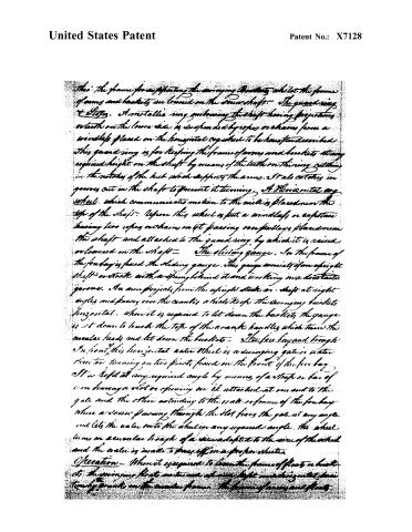
This: the frame for supporting the swinging brackets while the frame of arms and brackets are lowered on the drive shaft. The guard ring & Slots. A metallic ring embracing the shaft having projections or teeth on the lower side is suspended by ropes or chains from a windlass placed on the horizontal axle which to be hereafter described. This guard ring is for keeping the frame of arms and brackets at any required height on the shaft by means of the teeth on the ring catching in the notches of the hub which supports the arms. It also catches in grooves cut in the shaft to prevent it turning. A Horizontal axle wheel, which communicates motion to the mill is placed near the top of the shaft. Upon this wheel is put a windlass or capstan having two ropes or chains on it passing over pulleys placed near the shaft and attached to the guard ring by which it is raised or lowered on the shaft.
The sliding gauge. In the frame of the for-bay is fixed the sliding gauge. This gauge consists of an upright shaft or stock with a spring behind it and working in a horizontal groove. An arm projects from the upright stock or shaft at right angles and passes over the crank which keeps the swinging brackets horizontal. When it is required to let down the brackets the gauge is let down to locate the top of the crank handle which turns the circular body and let down the brackets.
The fire bay and trough. In front of this horizontal axle wheel is a swinging gate or water door to turning on two pivots fixed in the front of the fire bay. It is kept at any required angle by means of a strap or bar of iron having a slot or opening on it attached at one end to the gate and the other extending to the water or frame of the fire bay where a screw passing through the slot fixes the gate at any angle and lets the water into the sluice in any required angle. The wheel turns in a circular trough of a size adapted to the size of the wheel and the water is made to pass off in a proper sluice.
Operation — When it is required to lower the frame of floats or brackets the swinging float is turned up and kept in a horizontal position by cranks on the circular frame. The frame of arms and floats.
Page 4.
United States Patent
Patent No.: X7128
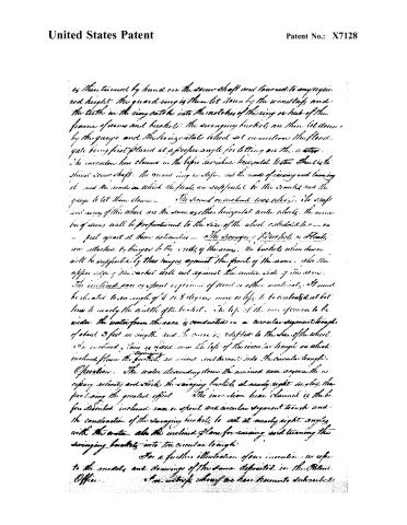
as then turned by hand on the screw shaft and lowered to any required height. The guard ring is then let down by the windlass and the teeth in the ring catch into the notches of the ring or hub of the frame of arms and buckets. The swinging buckets are then let down by the gauge and the horizontal wheel set in motion, the flood gate being first placed at a proper angle for letting on the water. The invention here claimed is the before described horizontal Water Wheel, the spiral screw shaft, the guard ring or stop, and the mode of raising and lowering it, and the mode in which the floats are supported by the cranks and the gauge to let them down.
The second or inclined race wheel, its shaft and arms of this wheel are the same as other horizontal water wheels. The number of arms will be proportioned to the size of the wheel calculated for — or — just apart at their extremities — The swinging Buckets or Floats are attached by hinges to the ends of the arms. The buckets when down will be supported by their hinges against the front of the arms. Also the upper edge of the ratchet will rest against the under side of the arm. The inclined race or spout or form of wood or other material. It must be situated to an angle of 6 to 8 degrees more or less to be contracted at bottom to nearly the middle of the bucket. The lips of the race or spout to be wider. The water from the race is conducted in a circular segment trough of about 2 feet in length and the curve is adapted to the face of the wheel. An inclined plane is placed near the top of the circular trough on which inclined plane the buckets are raised and thrown into the circular trough.
Operation. The water descending down the inclined race acquires the necessary velocity and strikes the swinging buckets at nearly right angles, thus producing the greatest effect. The invention here claimed is the before described inclined race or spout and circular segment trough and the construction of the swinging buckets to act at nearly right angles with the water. Also the inclined plane for raising and turning the swinging buckets into the circular trough.
For a further illustration of our invention we refer to the models and drawings of the same deposited in the Patent Office.
We witness, whereof we have hereunto subscribed.
Page 5.
United States Patent
Patent No.: X7128
This: The frame for supporting the swinging buckets, while the frames of arms and buckets are lowered on the drive shaft. The guard ring & stops. A metallic ring embracing the shaft having projections or teeth on the lower side is suspended by ropes or chains from a windlass placed on the horizontal axis which to be hereafter described. This guard ring is for keeping the frame of arms and buckets at any required height on the shaft by means of the teeth on the ring catching in the notches of the hub which supports the arms. It also catches in grooves cut in the shaft to prevent it turning. A horizontal cog wheel, which communicates motion to the mill is placed near the top of the shaft. Upon this wheel is put a windlass or capstan having two ropes or chains on it passing over pulleys placed near the shaft and attached to the guard ring, by which it is raised or lowered on the shaft.
The sliding gauge. In the frame of the fowley is fixed the sliding gauge. This gauge consists of an upright shaft or stock with a spring behind it and working in a horizontal groove. An arm projects from the upright stock on shaft at right angles and passes over the counter which keeps the swinging buckets horizontal. When it is required to let down the buckets, the gauge is set down to touch the top of the crank handle which turns the circular leads and let down the buckets.
The fire bay and trough. In front of this horizontal water wheel is a swinging gate or water door turning on two pivots fixed in the front of the fire bay. It is kept at any required angle by means of a strap or bar of iron having a slot or opening on it attached at one end to the gate and the other extending to the seat or frame of the fowley where a screw passing through the slot fixes the gate at any angle and lets the water onto the wheel in any required angle. The wheel lies in a circular trough of a size adapted to the size of the wheel and the water is made to pass off in a proper stream.
Operation — When it is required to lower the frame of floats or buckets, the swinging floats are turned up and kept in a horizontal plane by means of the counter frame. The frame of arms and floats.
Page 6.
United States Patent
Patent No.: X7128
is then turned by hand on the screw shaft and lowered to any required height. The guard ring is then let down by the windlass and the teeth in the ring catch into the notches of the ring or hub of the frame of arms and buckets. The swinging buckets are then let down by the gauge and the horizontal wheel set in motion, the flood gate being first placed at a proper angle for letting on the water. The invention here claimed in the before described horizontal water wheel is the spiral screw shaft. The guard ring is left, and the mode of raising and lowering it and the mode in which the floats are supported by the cranks and the gauge to let them down.
The second or inclined race wheel. The shaft and arms of this wheel are the same as the horizontal water wheel. The number of arms will be proportional to the size of the wheel calculated for — as — feet apart at their extremities — The swinging buckets or floats are attached by hinges to the ends of the arms. The buckets when down will be supported by their hinges against the front of the arms. Also the upper edge of the bucket will rest against the inside side of the arms. The inclined race or spout is formed of wood or other materials. It must be inclined to an angle of 6 to 8 degrees more or less to be contracted at bottom to nearly the width of the bucket. The lips of the race opposite to be wider. The water from the race is conducted in a circular segment trough of about 3 feet in length and the same is adapted to the size of the wheel. An inclined plane is placed near the lips of the circular trough on which inclined plane the buckets are raised and turned into the circular trough.
Operation. The water descending down the inclined race acquires the necessary velocity and strikes the swinging buckets at nearly right angles, thus producing the greatest effect. The invention here claimed is the before described inclined race or spout and circular segment trough and the condition of the swinging buckets to act at nearly right angles with the water, also the inclined plane for raising and turning the swinging buckets into the circular trough.
For a further illustration of our invention, we refer to the models and drawings of the same deposited in the Patent Office.
We witness whereof we have hereunto subscribed
Page 7.
United States Patent
Patent No.: X7128
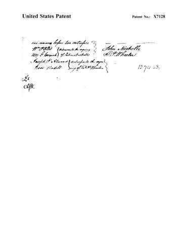
our names before two witnesses
Wm. O. Ellis Witness to the signing
Wm. J. Gounah of John Mitchell
Joseph P. Newood Witness to the signing
Jesse Andell Sing of P. & W. Wheeler
John Mitchell
J. P. Wheeler
1274 n8
A.
C. H. W.
Published accounts: journal notice
Notice in the monthly list of patents, with remarks
Journal of the Franklin Institute, new ser., vol. 11 (1833), p. 30 · View the page
35. For a Horizontal Current Water Wheel, and inclined race wheel; John Nuckalls, and Solomon P. Wheeler, Boliver, Hardeman county, Tennessee, June 22.
Remarks. Both these wheels have buckets which are suspended from horizontal arms projecting from a vertical shaft. The particular mode of fixing them could not be described without writing a longer article respecting them than we are just now inclined to produce, particularly as we do not see any thing in them which leads to the conclusion that they will surpass in usefulness other wheels of a similar character, and that is saying but little in their favour.
About this record
- Patentee
- DATAMP
- Date
- the Name and Date index of patents, DATAMP, USPTO records
- Invention
- DATAMP
- Listed in
- the Name and Date index of patents, DATAMP, USPTO records, Jim Shaw's X-patent list, the Journal of the Franklin Institute, Burke's List of Patents (1847)
- Burke's 1847 Patent Office list gives the same patent.