

Drawings and documents
National Archives restored drawings: drawing
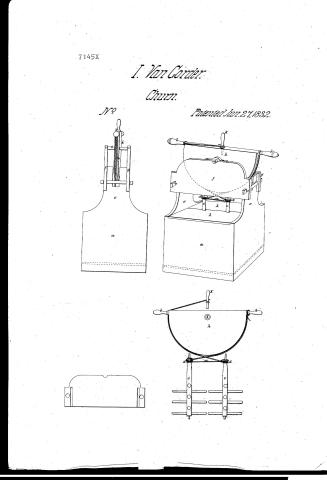
Isaac Van Gorder's Patent Drawing for an Improvement in the Churn

National Archives, Restored Patent Drawings (Record Group 241) · Full-size scan at the National Archives · Catalog record
Show the text on the drawing Hide (59 words)
Words on the drawing as machine-read by the National Archives; not checked. Useful mainly for searching.
Viliating soc, Churna / CLASSIONCATION / Churns. / 7145-+ / agr product to / DIV ISION. / Isaac Van Gorder / Improvement the Churn. / Protented June 1832. / wlate / plate. / who / wheel handle O with / I'm / Patint office Deefg 1841 / made / the / of Pater in conformity with act of Grandh / HL elemon
USPTO scan
The patent as scanned by the USPTO
-
 Page 1
-
 Page 2
-
 Page 3
-
 Page 4


U.S. Patent and Trademark Office · Google Patents
Show the transcription Hide (1,340 words)
Machine transcription (LightOnOCR) of the pages as scanned by the USPTO, most of them the handwritten copies made when the records were restored after the 1836 fire. Not checked; it can misread handwriting, so compare it with the scan.
Page 1.
7145X
I. Van Gorder.
Churn.
No.
Patented Jun. 27, 1832.
Page 2.
7145X
June 27, 1892
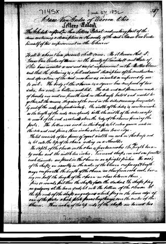
Isaac Van Gorder of Warren, Ohio
Letters Patent
The Schedule referred to in the Letters Patent and making part of the same containing a description in the words of the said Isaac Van Gorder himself of his improvement in the Cheese
To all to whom this presents shall come. Be it known that I, Isaac Van Gorder of Warren in the county of Summit and State of Ohio have invented a new and useful improvement in the Butter churn and that the following is a full and exact description of the construction and operation of the said machine as invented or improved by me to wit. The body of the churn is a square box composed of two sides, two ends, a bottom and lid. The side and end pieces are made of boards one and one fourth inch in thickness halved and nailed together at the corners, the grain of the wood in the sides running horizontally and of the ends perpendicularly. The width of the sides is seven inches as the length of the ends corresponds with the width of the sides except so much of the end as extends above the body of the churn forming the posts. The bottom one inch in thickness is let into a groove made in the side and end pieces three inches above their lower edge.
The lid consists of two pieces of equal width one inch in thickness and is let into the top of the churn resting on a shoulder.
The depth of the churn in the box is fourteen inches, the length twenty inches and the width ten inches. Two round shafts one and one fourth inch diameter are placed in the churn in an upright position. The axes of the shafts are exactly in the center of the churn one and one fourth ways one fourth the length of the churn in clear from each end, having one half the length of the churn in clear between them. Pins or rounds fasten the shafts to the stands. The shafts play on guidons at the lower ends let into the bottom of the churn. At the top ends of the shafts are guidons which play in the lower edge of one of the plates which plate passes lengthways over the center of the churn. Three inches of the top ends of the shafts are turned into
D. Van Gorder
Page 3.
and one fourth inches in diameter with a small projecting lip at the extreme left forming pulleys round which the cord passes. The pins are round, half an inch diameter and ten inches long. The number of pins in each shaft is six; the first pin is half an inch from the bottom, the second at right angles to the first, and one inch above it and so on alternately each cropping the one next to it at right angles with the space of an inch between. A post at each end of the chum for the support of the top works is formed by continuing the pieces low distance of ten inches above the top of the lid. The posts are seven-eighths of an inch in thickness and four and a half inches wide at the top. The lower part of the post near the body of the chum may be made wider than the top or not to suit the fancy of the workman. Two plates ten and three fourths inch is wide and one inch in thickness pass over the chum length ways tied together at each end by a round or girt passing between the plates close to the inside of the posts. The top edge of the plate is taken out at each corner with a quarter circle so as to leave it but four and a half inches wide at each end where it rests on the posts. A groove corresponding in width to the thickness of the post and three eighths of an inch deep is made in each end of each plate where it comes against the post and each edge of the posts at the top end is cut off five eighths of an inch wide as low down as the bottom of the plates with a square shoulder for the lower edge of the plate to rest on. A piece of the top of the post in the centre is taken out one and a half inch wide and three and a half inches down for the edges of the wheel to play thru. The lower edge of the plate is five and a half inches from the top to the lid. The wheel is formed of a single board and is a segment of nearly six tenths of a circle of six inches diameter. The thickness of the wheel is one inch two semicircular grooves of suitable size for a cord. A fourth of an inch diameter are cut in the edge of the wheel round the circular part. Three handles are attached to the wheel to work it by one in the the centre of the straight line
Page 4.
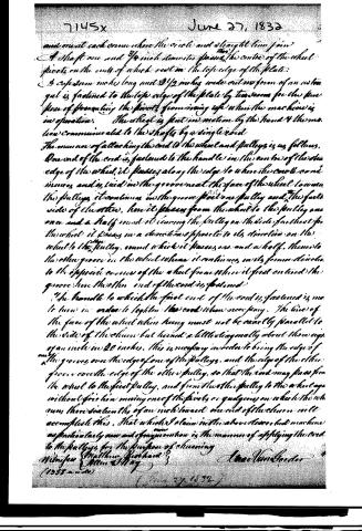
and meet each other where the circle and straight line join. A shaft one and 3/4 inch diameter passing through the centre of the wheel pivots on the ends of which rest on the top edge of the plate. A case seven inches long and 2 1/2 inches wide cut in form of an umbrella is fastened to the top edge of the plate by two screws for the purpose of preventing the pivots from rising up when the machine is in operation. The wheel is put in motion by the hand and the motion communicated to the shaft by a single cord. The manner of attaching the cord to the wheel and pulleys is as follows. One end of the cord is fastened to the handle in the centre of the other edge of the wheel; it passes along the edge to where the circle comes in, and is tied in the groove near the face of the wheel towards the pulleys; it continues in the groove past one pulley and the far side of the other, hence it passes from the wheel to the pulley one over and a half round it leaving the pulley on the side farthest from the wheel; it passes in a direction opposite to its direction on the wheel to the pulley, round which it passes one and a half, thence to the other groove in the wheel where it continues in its former direction to the opposite corner of the wheel from where it first entered the groove; hence the other end of the cord is fastened. The handle to which the first end of the cord is fastened is made to turn in order to tighten the cord when necessary. The line of the face of the wheel when hung must not be exactly parallel to the side of the column but turned a little diagonally about three eighths of an inch in 20 inches. This is necessary in order to bring the edge of the grooves over the edges of one of the pulleys, and the edge of the other groove over the edge of the other pulley, so that the cord may pass from the wheel to the first pulley, and from the other pulley to the wheel again without friction moving over the pivots or gudgeons on which the wheel runs; three tenths of an inch toward one end of the column will accomplish this. That which I claim in the above described machine as particularly new and original is the manner of applying the cord to the pulleys for the purpose of running.
Witness Matthew Gerhard
(1255 words)
June 27, 1832
Published accounts: journal notice
Notice in the monthly list of patents, with remarks
Journal of the Franklin Institute, new ser., vol. 11 (1833), p. 37 · View the page
50. For a Churn; Isaac Van Gorder, Warren, Trumbull county, Ohio, June 27.
Remarks. In this churn there are to be two vertical shafts, each of them carrying arms, or dashers, which in their revolution, or vibration, pass between those of its fellow. Upon the top of each of these shafts there is a whirl, or pulley, having a rope passing round it, the ends of which ropes are attached to the periphery of a vertical wheel. By giving a vibratory motion to this wheel, the shafts and dashers are caused to revolve. The claim is to "the manner of applying the cord to the pulleys for the purpose of churning." The manner of doing this, it will be seen, resembles that of another churn patented on the second of this month, (June,) see No. 5. It may be observed that both the patentees reside in the same place. The main difference in the churns consists in the use of double dashers in the last; another churn, similar to these, was contributed by New Hampshire, on the 22d inst. (No. 28,) which has the same moving apparatus, and a single shaft.
About this record
- Patentee
- DATAMP
- Date
- the Name and Date index of patents, DATAMP, USPTO records
- Invention
- DATAMP
- Listed in
- the Name and Date index of patents, DATAMP, USPTO records, Jim Shaw's X-patent list, the Journal of the Franklin Institute, Burke's List of Patents (1847)
- Burke's 1847 Patent Office list gives the same patent.