

Drawings and documents
National Archives restored drawings: drawing
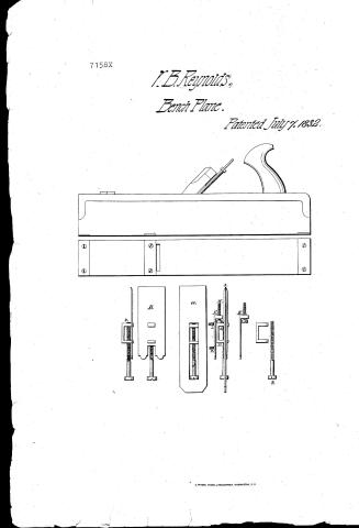
W. B. Reynold's Patent Drawing for a Double Iron Trying Plane

National Archives, Restored Patent Drawings (Record Group 241) · Full-size scan at the National Archives · Catalog record
Show the text on the drawing Hide (165 words)
Words on the drawing as machine-read by the National Archives; not checked. Useful mainly for searching.
145. WOOD WORKING. / 4. TOOLS. / We / 29] Bench Pl / Bench / Pleases / $2 / CLASSIFICATION / W. B. Reynoldo / 7158-7 / DIVISION. / Double Iron Trying Plane. / Pat: 7 Jaly:1832. / F.B.ael... / XXXXXXXXXX / 00000 / Ohio County / State of Virginia / for / On the 29 of May Eighteen hundred und thirty seven before / the subscriber a justice of the peace, came William B Reynolds, and made / solemn oath acording to law, that he is interested, as inventer of an improve / ment in the double Iron toging planes, which he states is part in the bits, / and part in the stock, Known by the name of the double Iron double guarded / setscrews, and that he had a patent, easued to him, on the seventh day of / July, one thousand Eight hun ed and thirty two, and the above drawings, with / reference thereto, are, as he verify believes, a true delineation of the inveation, / as described in the letters patent / Geo Duty. J.P.
USPTO scan
The patent as scanned by the USPTO
-
 Page 1
-
 Page 2
-
 Page 3


U.S. Patent and Trademark Office · Google Patents
Show the transcription Hide (823 words)
Machine transcription (LightOnOCR) of the pages as scanned by the USPTO, most of them the handwritten copies made when the records were restored after the 1836 fire. Not checked; it can misread handwriting, so compare it with the scan.
Page 1.
7158X
V.B. Reynolds,
Bench Plane.
Patented July 7, 1832.

Page 2.
71587
July 7, 1892
William B. Reynolds, of Blairsville, State of Ohio.
Letters Patent.
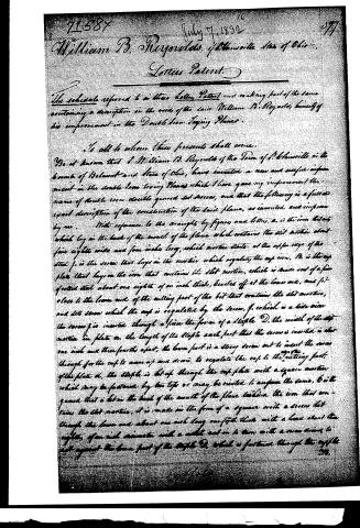
The schedule referred to in these Letters Patent now making part of the same containing a description in the words of the said William B. Reynolds himself of his improvement in the Double Iron Tipping Planks.
To all to whom these presents shall come.
Be it known that I William B. Reynolds of the Town of Blairsville in the County of Belmont and State of Ohio, have invented a new and useful improvement in the double iron tipping Planks which I have given my improvement the name of double iron double geared set screws, and that the following is a full and exact description of the construction of the said plank, as invented and improved by me.
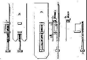
With reference to the drawings by figures and letters, a. is the iron block which lay in the back of the mouth of the plank which contains the slot mortise about five eighths wide and four inches long, which mortise starts at the upper edge of the steel f. is the screw that lays in the mortise which regulates the cap iron. B. is the cap plate that lays on the iron that contains the slot mortise, which is made out of a fine grained steel about one eighth of an inch thick, beveled off at the lower end, and f. is close to the lower end of the cutting part of the bit that contains the slot mortise, and sets screw which the cap is regulated by the screw, f. which is a side view the screw f is inserted through a piece the form of a staple D. the width of the slot mortise in plate a. the length of the staple each part that the screw is inserted is about one inch and three fourths apart, the lower part is a strong screw out to insert the screw through for the cap to move up and down, to regulate the cap to the cutting part of the plate a. the staple is let up through the cap plate with a square mortise which may be fastened by two teps or may be riveted to answer the same, b is the gear that is let in the back of the mouth of the plank behind the iron that contains the slot mortise, it is made in the form of a square with a screw let through the lower end about one inch long one fifth thick with a head about two eighths of an inch diameter with a notch cut in to turn with a screw moving to act against the lower part of the staple D. which is fastened through the cap plate.
Wm. B. Reynolds
Page 3.
B. which it helps the bit when placed in the plane from setting too deep, H. is the screw in the guard K, about a fourth thick one inch long, being about three eighths diameter with a notch cut in a screw driver to turn with up or down to act as a guard against the bone out of the staple D. that is fastened to the cap plate H. for the purpose of regulating the depth of the set of the bit when the plane is in use, the guard K, is about five eighths, and one fourth thick, three inches and one fourth long at the bone end where the screw is let through, is about three eighths thick, for the purpose of strength, it is let into the back of the mouth of the plane, about three fourths deep exactly in the center of the mouth, and secured fast by two wood screws. F. 2. the set screw, it is made exactly the length of the slit mortice about one fourth thick, with a thick strong head three eighths diameter, with a notch to receive the screw driver to regulate the cap. The thread is cut up from the point about two inches and a half, and slipper through a smooth hole in the upper part of the staple D. to the lower end at F. 6, which a strong thread is cut through to receive the screw by turning it the cap moves up and down to regulate the set of cap plate when F. 3. is the view of the cap plate bit and guard when put together placed together, in the plane ready for work & 4. is a side view of cap plate staple and set screw to show the plan they are united together. Dated the 2nd 1822, Milroy
William Shannon
W. C. Gansling
Sterling Shuttow
William B. Reynolds
768 21 52
(Patented July 4, 1822)
Published accounts: journal notice
Notice in the monthly list of patents, with remarks
Journal of the Franklin Institute, new ser., vol. 11 (1833), p. 94 · View the page
5. For an improvement in the Double-iron Plane; William B. Reynolds, St. Clairsville, Belmont county, Ohio, July 7.
Remarks. Although some pains have been taken by the writer of the description of this improvement, it is yet somewhat obscure. The object, however, is to use set screws to adjust pieces upon the plane iron so that they shall fit into corresponding mortises on the cap iron, in order that it may at once fall into its right place. The mode of effecting this, seems to us more complex than necessary. We have, in fact, seen a much more simple arrangement for the same purpose; still, the common method is certainly susceptible of improvement.
DATAMP: illustration
Illustrations from DATAMP

DATAMP (Directory of American Tool and Machinery Patents), via the Internet Archive · Archived DATAMP page
About this record
- Patentee
- DATAMP
- Date
- the Name and Date index of patents, DATAMP, USPTO records
- Invention
- DATAMP
- Listed in
- the Name and Date index of patents, DATAMP, USPTO records, Jim Shaw's X-patent list, the Journal of the Franklin Institute, Burke's List of Patents (1847)
- The X number was worked out from the patent’s place in the date sequence.
- Burke's 1847 Patent Office list gives the same patent.