

Drawings and documents
National Archives restored drawings: drawing
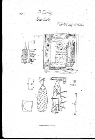
Boyd Reilley's Patent Drawing for a Vapour Bath

National Archives, Restored Patent Drawings (Record Group 241) · Full-size scan at the National Archives · Catalog record
Show the text on the drawing Hide (31 words)
Words on the drawing as machine-read by the National Archives; not checked. Useful mainly for searching.
BATHS & CLOSETS. / yd Reitley's Vapour Bath / Patented July 31 183. / CLASSINCATION / 7190-+ DIVISION. / A. / DIA
USPTO scan
The patent as scanned by the USPTO
-
 Page 1
-
 Page 2
-
 Page 3
-
 Page 4
-
 Page 5
-
 Page 6
-
 Page 7
-
 Page 8
-
 Page 9
-
 Page 10
-
 Page 11
-
 Page 12
-
 Page 13
-
 Page 14
-
 Page 15
-
 Page 16
-
 Page 17


U.S. Patent and Trademark Office · Google Patents
Show the transcription Hide (5,901 words)
Machine transcription (LightOnOCR) of the pages as scanned by the USPTO, most of them the handwritten copies made when the records were restored after the 1836 fire. Not checked; it can misread handwriting, so compare it with the scan.
Page 1.
7190X
B. Reilley.
Vapor Bath.
Patented July 31, 1832.
Page 2.
No. 7190X
July 31, 1832 35
Boyle Reilly
The Schedule referred to in the Letter Patent and making part of the same, containing a description in the words of the said Boyle Reilly himself of his improvement in apparatus for applying either double or medicated vapors or steam to the surface of the human body, being an improvement on his former Patent dated February 5th 1831.
To all to whom these Presents may come. Be it known that I Boyle Reilly of the City of Philadelphia in the County of Philadelphia and State of Pennsylvania having obtained Letters Patent on the 6th day of February one thousand eight hundred and thirty one, for a new and useful improvement in apparatus for applying either simple or medicated steam to the surface of the human body with perfect ease and safety in the absence of the sick; having made considerable improvements in the same of which the following is a full and exact description. Note 1st Figure A represents a machine which separates into three divisions, each part calculated to fit easily into the other, by which the length of the machine, when packed up, is reduced nearly two thirds without a saving to the shipping. The top cover appears raised at the side, to show the three boxes by which it is supported; the foot division is attached to show the fastenings by which it is united to the center division; the false bottom is also attached, as it necessarily must be to permit the separation of the foot division. The shape of the frame is an egg oval: at the head a false round, to accommodate the shortness of the patients; at the foot made more acute for the convenience of packing up also to afford as much room as possible to the sides in order that the top and bottom covers may pass the closer. The divisions of the frame are in length as follows: the head division 20 inches and a
Page 3.
July 31, 1832
half that distance, the middle division 2 inches, & the fore division 1½ inches and a half. The frame of the middle division is made of seasoned wood, oak cherry &c. the six pieces of this frame, 4 inches in depth & ⅜ of an inch in thickness; the lengths already given; they are excepted from the part of the seat they belong to. A slatting rail of the same breadth and thickness is connected into each one of the frame, the one at the upper end 25 inches in length, the one at the lower end twenty-three; these slatting rails are hollowed out from the upper edge three inches in the centre to make room for the body of the patient; they are glued in & further secured by a wooden pin passing through the down tails from top to bottom, that is 4 inches. The head division is formed by a piece of hickory or white oak (if green it will bend better) 4 inches in depth and three quarters of an inch in thickness, bent to the shape of the head of the frame on a block or frame, after being prepared by boiling or steaming, and then dried in the sun or with a fire to keep it in shape; the ends are secured by a slatting rail ⅜ of an inch in thickness and to correspond in shape with the one in the middle division. The fore division is formed by a similar bent piece made to the shape of the acute end of the seat & five eighths of an inch in thickness. Slatting and the same; these bent pieces are lightened on the bottom edge between the down tails, to a half inch in thickness.
The patient reclines on broad girths or "straining rails" as described in my former specification, some change in the division if it is necessary in consequence of the division of the frame. This is shown on plate 10 figure 13. The numbers are made to receive the girths when eight or ten inches from the upper edge of the frame, it is to be observed that the girths are invariably entered from the inside of the frame which will prevent the patient's knees to the breadth of the
Page 4.
July 31, 1832
girdling. The girdling being taken out whenever this machine is broken up, the ends are fastened with a strap and buckle of inch and half girdling or leather. They should be strong with buckles livened or plated, and attached by a strap to the frame. A piece of strong blanket 12 inches in breadth is extended along the centre of the girdling and fastened by the ends, lapping under and taking a large horn button on the outside of the frame. Two circular bottoms or iron bags are made in breadth over one eighth of an inch depth in the centre except at the head of the frame, where they should be gradually descended to permit the piece that supports the cushion for the head of the patient to move up and down; the use of these bottoms being to receive the edges of the top and bottom covers.
One of these bottoms is a full eighth of an inch from the bottom of the girdling mortices, the other is the same distance from the lower edge of the frame. The upper edge of the frame and the girdling mortices must be made round and smooth so as to keep the girdling from chafing.
The bottom of the middle division is covered with stout sheet tin turned close to the bottom on the sides but projecting a quarter of an inch at each end to cover the joints when the end divisions are attached; the projecting ends should be doubled, to give them strength and the end edge should be returned under the frame to protect it from the action of the vapours. The head and feet divisions may be covered with a lighter tin as all unnecessary additions to the weight of the machine should be avoided; the bottom of the head division should be perforated with twelve half inch holes one inch apart, close to the inside of the head of the frame; these holes are to permit the escape of the vapours between the bottoms. The tin bottoms are fastened on with stout iron tacks which should be tinned. The frame and bottoms should be painted with some strong colour not extracted from lead.
Page 5.
The end divisions are attached to the middle division by strong wrought iron hooks, rivetted into plates of stout sheet iron, the long or rivet end being made square in order to prevent its turning; the plates with the hooks attached, are let into the stretching rails of the end divisions three inches from the ends or outside of the frame, as near to the lower edge as the strength of the plates will admit of, as the fastening when pressed by the weight of the patient, draws the joints above; these plates are secured by a stout flat headed screw at each corner; the hooks should not project more than five eighths of an inch from the plates, lest they should penetrate those of the opposite stretching rail, and be exposed to the vapours; these hooks are received by similar stout iron plates let into the opposite stretching rail; and when the hook at the bottom is pressed, after it has entered the plate, these fastenings should be well turned. The bars which support the top cover, are made of hickory or white oak, they are made round and half an inch in diameter, the bar for the head must not exceed the length of the middle division, as it must be packed up inside of the case. It is fastened by passing the ends through the two stretching rails, near at the head and close to the inside of the head division, which will cause it to be let into the side of the middle division one eighth of an inch, being the difference in thickness; the bars are bored that the stretching rails in such a direction as to elevate the centre of the bar if inserted above the top of the frame; the centre of the bars should stand in two inches from a line that would be perpendicular to the outside of the head of the frame. The centre bar is like the head bar in shape, but wider in space as occupying the widest part of the frame; it ranges on the top in straight line with the head and foot bars; it is placed at the upper end of the centre gripping motion and not at the lower end, unnecessarily marked on the
Page 6.
7190x July 31, 1832 39
dressing) is so fastened by hanging it into the side piece on a garter of an inch, the bottom of hanging down the side is within an inch of the bottom; a tin plate or half circular frame covers the ends and is fastened on with tin locks. The foot box is bent to the shape of the foot of the machine, fastened like the hand box, is elevated 15 inches from the top of the frame and stands 4 1/2 inches from the perpendicular line, which permits the cover to be put on and taken off with ease. The head of the patient rests on a circular board, 6 inches in diameter, covered and softly stuffed with wool or curled hair; a tin socket is fastened on the bottom of the board one inch from the edge, this socket is one inch and half in depth and is made to receive the end of a sliding stick 11 inches in length, one inch and a quarter in breadth and five eighths in thickness, rounded on one side to a half circle, the flat side rests against the head of the machine and is kept in its place by a loop socket, fitting round it & fastened with screws to the head of the frame; a short thumb screw is let into the center of the socket which keeps the cushion elevated or depressed at the pleasure of the patient. This fastening will be better understood as the familiar fastening of a barber chair; it is much more simple and cheap than the one on my model. The best material I have found for the cover is light twilled muslin, it should be stretched on a frame the twilled side within or from you a coat of white wash laid on first; made of good Spanish whiting and of such a consistency as not to run through the edges of this first coat being to prevent the preparation thereafter sometimes running through before the white wash has time to dry, follow with a light coat of the following preparation. In the second mentioned in my first specification was done when sufficient to give it a smooth body, not so strong however as if for common service. Lay on a sufficient number of coats to clear up the grain of the linen.
Page 7.
which can be ascertained by holding it against the light.
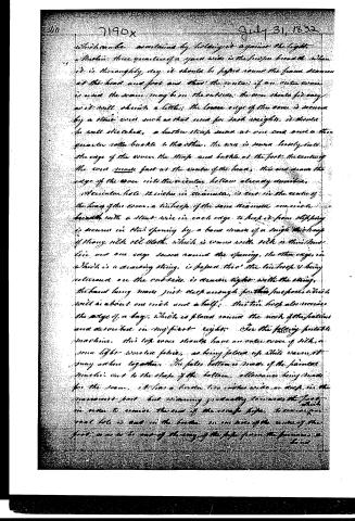
Make three quarters of a yard wide in the proper breadth. When it is thoroughly dry it should be papered round the frame, secured at the head and foot and then the cover, if an outer cover is used, the seam may be on the outside; the cover should fit easy as it will shrink a little; the lower edge of the cover is secured by a stout cord such as that used for sack weights. It should be well stretched, a leather strap sewn at one end and a three-quarter inch buckle to the other. The cord is sewn loosely into the edge of the cover, the strap and buckle at the foot. The center of the cover made fast at the center of the head. This cord draws the edge of the cover into the circular hollow already described.
A circular hole 12 inches in diameter is cut in the center of the head of the cover, a tube of the same diameter one inch in breadth with a stout wire in each edge to keep it from slipping is secured in this opening by a band made of a single thickness of strong silk cloth, which is sewn with silk or thread, and one edge sewn round the opening, the other edge, in which is a drawing string, is passed through the tube. The band being made just snug enough for this purpose, which will be about one inch and a half; this tube loop also receives the edge of a bag, which is placed round the neck of the seat and described in my first right.
For the filling portable machine, this top cover should have an outer cover of silk or some light woven fabric, as being folded up while warm it may adhere together. The false bottom is made of the painted material cut to the shape of the bottom, allowance being made for the seam. It has a border two inches wide on each side, in the narrowest part but widening gradually towards the foot. In order to receive the end of the escape pipe, a circular hole is cut in the border, on one side of the center of the foot, so as to be out of the way of the pipe from the furnace.
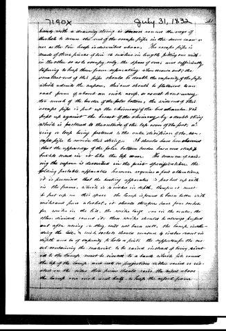
Page 8.
hanging with a drawing string is passed round the edge of the hole to secure the end of the escape pipe in the same manner as the tin hoop is described above. The escape pipe is made of three pieces of tin 12 inches in length, fitting one within the other so as to occupy only the space of one; and sufficiently tapering to keep them from separating when drawn out; the smallest end of this pipe should be double the capacity of the pipe which admits the vapour, this end should be flattened to one oval form of about an inch acrop, so as not to cut away too much of the border of the false bottom, the wideness of this escape pipe is just up the chimney of the hot chamber. It is kept up against the breast of the chimney by a double string which is fastened to the outside of the top cover of the pot, a ring or loop being fastened to the outer division of the escape pipe to receive this string. It should have been observed that the upper edge of the false bottom border has a cord strap & buckle sewn in it like the top cover. The manner of raising the vapour is described in the first specification, the folding portable apparatus however requires a few alterations, it is provided that the heating apparatus is pocketed up within the frame, which is 4 inches in depth, therefore it must be put up in this space. The lamp is found to burn better with wicks and pure alcohol, it should therefore have four sockets for wicks in the lid, the wicks large one in the centre, the other divided round it; these wicks should be always kept out after using or they will not burn well. The lamp, including the lid, & wick sockets should measure 4 inches round in depth and 6 in capacity to hold a pint. The supports for the vessel containing the material to be raised instead of being riveted to the lamp must be riveted to a band which fits round the top of the lamp and rests on projections in the rim or riveted on the sides. This frame should raise the vessel above the lamp one inch and half, to keep the vessel from
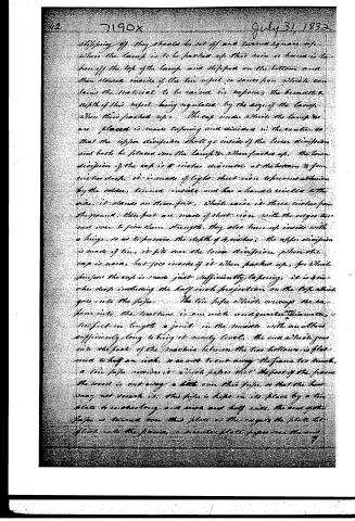
Page 9.
slipping off, they should be set off and turned square up. When the lamp is to be packed up, there must be a handle to take off the top of the lamp and slipped on the bottom and then screwed inside of the tin vessel or sauce pan which contains the material to be raised in vapours, the breadth and depth of this vessel being regulated by the size of the lamp when thus packed up. The cap under which the lamp is placed is made tapering and divided in the centre, so that the upper division shall go inside of the lower division and both be placed over the lamp when packed up. The lower division of the cap is 8 inches diameter at the bottom and four inches deep. It is made of light sheet iron reinforced by the solder, turned inside and has a handle soldered to the side. It stands on three feet, which raise it three inches from the ground. These feet are made of sheet iron with the edges turned over to give them strength. They also turn up inside with a hinge, so as to preserve the depth of 4 inches; the upper division is made of tin. It fits over the lower division when the cap is used, but goes inside of it when packed up, for which purpose the cap is made just sufficiently tapering. It is 4 inches deep including the half inch projection on the top which goes into the pipe. The tin pipe which conveys the vapour into the machine is one inch and a quarter diameter, two feet in length, a joint in the middle with an elbow sufficiently long to bring it nearly level. The end which goes into the foot of the machine between the two bellows is flattened to half an inch, so as not to cut away the frame too much. A tin pipe receives it which passes that the foot of the frame the wood is cut away a little over this pipe, so that the heat may not scorch it. This pipe is kept in its place by a tin plate 4 inches long and six and a half wide. The end of the pipe is turned over this plate as the cigar of the plate let itself into the frame, a similar plate passes over the end.
Page 10.
of the pipe inside of the frame, it is fastened with turned tacks; the pipe should project over this plate one inch to keep the hot gas from scorching the wood. The pipe is secured from being pushed out by a large plate somewhat longer than the tube which is fastened by four small wood screws.
The machine is prepared for use by first attaching the end wings, putting on the false bottom, drawing the strap and buckle tight at the foot; place the four chairs under the joints, taking care not to put them under the bottom farther than necessary to make it steady, as they will obstruct the passage of the escaping vapor. It is a good way to place the patient first, then fix the chairs; the center of the fitting should be marked, so that the ends may come out even. The fitting should be tightened by a piece, like a locking bottom screw; a sheet of stout blanket is in the middle, goes on the center of the fitting from head to foot and is fastened by a strap of narrow fitting, and a large bow button sewn on the bottom of the blanket at both ends. The tin hook which is round the patient's neck should be fastened in its place in the cover, and the loose edge of the cover put in its place at the head of the machine, so that the cushion for the head of the patient may be screwed in its place. The cover is then put on the floor at the head of the machine, until the hoops or bows are put in their places over the patient, when the cover is turned over the edges placed in the bottom, and the strap and buckle drawn tight. The bag which has been previously placed round the patient's neck is then secured round the tin hook by fastening the drawing string carefully between the wire edges; the escape pipe is then attached and the lamp lighted.
Should the patient have flannel, it had better be taken off. Should the person be so tall that his feet will come over the opening at the foot, he should be allowed to separate them. The machine is fastened up by placing the foot wings on each side of the machine.
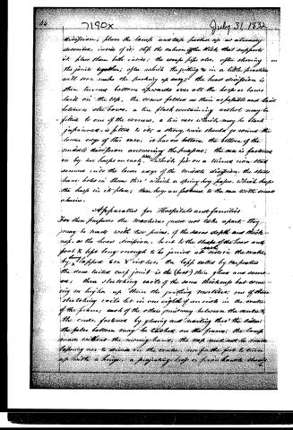
Page 11.
division, place the lamps and case packed up as already described, inside of it. Slip the cushion off the stick that supports it. Place them both inside; the cases slip also, often showing the joints together; often which the putting up in a little practice will soon make the packing up easy. The lower division is then turned bottom upwards over all the hoops or boxes laid on the top, the corners folded as thin as possible and laid between the boxes. A tin flask containing alcohol may be filled to one of the corners, a tin case which may be black japanned, is filled to it; a strong wire should go round the lower edge of this case; it has no bottom, the bottom of the middle division answering the purpose; the case is fastened on by two hoops on each, the third fits on a turned iron stick screwed into the lower edge of the middle division, the sticks have holes in them through which a spring key passes, which keeps the hoop in its place; these keys are fastened to the case with small chains.
Apparatus for Hospitals and families
For these purposes the machines need not take apart; they may be made with two pieces, of the same depth and thickness as the lower division, bent to the shape of the lower and foot & legs long enough to be joined at either the center by flapped 6 or 8 inches, the legs nailed by carpenters the same nailed each joint is the (best) then glued and secured; three slatting rails of the same thickness but coming no higher up than the jointing mortises; one of these slatting rails let in one eighth of an inch in the center of the frame; each of the other midway between the center & the ends, fastened by gluing and nailing thru the sides; the false bottom may be tacked on the frame; the lamps made without the moving band; the case need not be made leaving nor to divide on the center, nor for the feet to turn up but to a hinge, a projecting leg or false bands should
Page 12.
7190X
July 31, 1832 43
be fixed to the centre of each side; and the partition mortises may be brought at least one inch nearer together and an additional mortise cut on each side.
A fixed apparatus.
As shown on Plate 2, it is an oblong frame 6 feet long from out to out, by two feet six inches wide & 6 inches deep: the frame is made of two thicknesses of seven eighths white pine, stuff glued together; the top and heart edge being carefully put together, to keep it from springing. The circle round the neck 14 inches in diameter; a projecting wooden rim receives the bag round the neck, the rim projects one inch, is three quarters thick, should be slightly hollowed on the outer edge, to receive the drawing string and keep the bag from slipping; the inner edge should be rounded smooth. The bag should be increased in depth in proportion to the increase of diameter; the head of the frame should be carried up by a bowl two inches into the circle & the rim separated accordingly to leave a space for the neck to pass through on putting on the cover, a covering or other covering 4 inches deep from the upper edge is fast round the frame, leaving an inch at the lower edge to fasten a fastener or balance to. A ledge of shagogany three quarters of an inch thick and wide enough to cover the edge and project to form a mounting, is fastened all round the upper edge of the frame and fitted of course at the corners. The cover is circular, it may be covered a maximum width of line 18 inches high from the straight line at the ends; the ends of the cover made of seven eighths white pine in two thicknesses the grain of inside thickness running up and down; then ends connected by side pieces made like the side pieces of the frame below, and secured at the corners in the same manner; the circular top is covered by strips of half inch pine running from head to foot.
Page 13.
The breadth of a V-riple will vary according to the length of the circle they cover; the edges, of course, beveled so as to joint. A covering of strong linen is drawn over these strips, glued or fastened and fastened on the outside, the whole top being neatly covered with any tapestry that the fancy may suggest. The escape of the gas is prevented by a cone given the shape of which is given on the drawing. The cone is one inch wide and three eighths deep. The hollow is worked in the legs on the upperage of the frame, a pine tongue is fitted into this hollow. The upper part is then glued and the cover being immediately secured thereon. When the glue dries, the cone will be exactly in its place; the whole lower edge of the cone, including the cone, is covered with even soft cloth, and the cone is made fast when in use by two trap hasps on each side, made on the same principle as the hasp of a trunk lock, the hasp being attached to the cover, the receiving plate let into the side of the frame. The drawing shows the top suspended by cords and counterweights. The cords pass through pulleys fixed directly over them in the ceiling and are then fastened to weights which are contained midway four hollow pillars which support the canopy and curtains. The cover may attached by hinges on the back parts like the lid of a chest. The bottom of this apparatus is tied to its rests on six legs, it inches long, three on each side. The vapour is admitted through a two inch pipe running up through the leg at the back part of the foot of the machine, the vapour passes out through both the legs at the head of the machine. These legs may be made of oak, pine, or maple, which will have a cavity of two inches. They are covered by the canopy within an inch of the bottom and may have some neat finish on the part of the leg that is seen. The apparatus stands on a platform a certain height, the platform being
Page 14.
form projects beyond the apparatus at the front side and at each end, so as to leave room for a person to walk round, the distance is left to the taste of the maker; the platform extends to the wall or partition at the back side of the machine, leaving a space to pass behind and adjust the oven. The platform also assists in bracing the columns which sustain the curtains. The two legs at the head are attached to a wooden pipe of the same size which passes under the platform through the wall or partition in the rear & communicates with a chimney or perpendicular flue of some height out of doors. The two pipes which run through the legs at the foot of the machine pass by an elbow under the platform & communicate with the furnace which may be in the cellar or out of doors. Should there however be a fire place in the room so situated as to answer, it will save trouble; the furnace is heated by charcoal which is burned in a small sheet iron stove, similar to that used by tin manufacturers to heat their soldering irons, a circular sheet iron stove is placed over this with a door large enough to receive a vessel containing the materials to be raised in vapors. This door slides upwards to be raised or lowered at pleasure so as to admit a greater or less quantity of air; a flange and short pipe is attached to the back of this stove or to the top of it, as the case may be, which communicates with the tin pipe already mentioned. The furnace of the charcoal should have a vent back and not be permitted to enter the machine on account of the smoke. The patent requires on a frame made of two pieces of ebony or similar wood to the width and one inch thick. The length of the inside of the machine these pieces placed on edge on each side of the machine are united by four stretching pieces of the same thickness and reaching up to a range of grating movable from and
Page 15.
finished like the cage of the apparatus last described. The stretching piece at the head and foot frames 6 inches from each end; the other two equally divided, the stretching pieces lightened or hollowed out to within one inch and half of the bottom. This frame can be taken out to dry the girdling after using. Holes must of course be made thru' the two bottoms to communicate with the legs that are used for the traps. The bottom is made fast to the legs by nailing. These openings in the bottom are covered by a piece of tin at each end 6 inches wide and extending across the bottom. These pieces are edged with strong wire and furnished full of hooks, in the side of one edge several hinge pieces are placed, which are fastened by twisted nails or screws to the end pieces of the frame, so far up as to make the tin frame an angle with the corners.
The head cushion and supporter of this apparatus are made like the head one on my model, the cushion may be made larger and trimmed with more taste. This apparatus is painted with ocher.
Portable Machine for the Girdle
The bottom part is made of sheet tin, it is two feet long by one foot wide and four inches deep. It has a stout wire in the edge turned on the inside, the lid or top is two inches deep and when closed laps over the bottom one inch and is fastened by two hooks on each side like a commode, when in use the top is supported by a light trap joint in each corner, similar to a rule which when struck falls towards the centre within the sides of the machine. The vapors are raised and conveyed off in the same manner as the portable machine for the body, the long top pipe may be made smaller. The vapors is admitted thru' a flattened hole close to the bottom at the end of the machine opposite the
Page 16.
July 31, 1832
site to when the limb is admitted, a flat pipe or passage 4 inches wide and half an inch high is opened on the bottom from this hole to the front of the machine, a range of small holes are punched in the half inch edge of this passage by which the vapors are spread through the machine without coming in a body in contact with the limb by which it might be scalded.
When the machine is in use a space of 12 inches is preserved by the screw joints between the cage of the top and bottom, the vapors is confined by an oil cloth prepared in the same manner as the cover of the portable machine, a circular opening is made in the and 10 inches in diameter, the bottom of the circle being even with the edge of the bottom, to the edge of which a bay is sewed, similar to those just round the neck of the patent in the other machine, like that laid in folds round the limb and secured by a handkerchief. This oil cloth is secured at the bottom by being tucked round the outside of a wooden frame, which is made of pieces one inch wide and half an inch thick, these pieces are fitted (with their edges up and down) to the inside of the bottom, allowance being made for the thickness of the oil cloth and for pieces of the same breadth (one inch) and the thickness of the wire projecting on the inner edge of the bottom.
This frame is double tiered at the corners and fastened by round headed screws, which fast the sides and ends, then the filling of strips the thickness of the wire already mentioned into the frame, the lower edge of which is one inch from the bottom, and half an inch from the passage which receives the vapors. The top edge of the oil cloth is tucked to the edge of a frame of the same breadth and thickness, which is fitted up flat against the inside of the top of the box or cover and fastened.
Page 17.
7190x
July 31, 1832
and with round heads secured to the top. The frame is copper half and half at the corners all around leaving to be made for the thickness of the iron or steel plate as the stiffening wire here is on the out side of the oven.
The escape pipe is made in joints and goes into the back part of the oil cloth, over the furnace pipe and close to the upper edge of the bottom secured in the same manner as that of the large machine. A handle is fixed in the center of the top. A support for the limb is made of stout iron attached by a hinge to the wire in the edge of the bottom, and under the opening for the limb; this support may be 8 inches long and 4 wide; is stuffed on the top, and turned inside of the machine when closed up; a cushion covered with oil cloth is also made for the feet to rest on; it is attached to a tin stand in the form of a stool; the feet going on each side of the vapour receiver, and one inch high, which keeps it half an inch from the hot pipe. The inside well painted with ocher the outside black japanned. The machine rests on two other axes.
References to improvement:
Plate 1st Figure A. Large portable apparatus.
ditto ... ditto B. Another view of the same.
ditto ... ditto C. Machine packed up.
ditto ... ditto D. Side view for ditto.
ditto ... ditto E. Escape pipe drawn out.
ditto ... ditto F. Improved axis.
ditto ... ditto G. Lamp fixed for use.
ditto ... ditto H. ditto packed up.
ditto ... ditto I. Stacking coils of factory with holes for many turns.
Plate 2nd Figure A. Fixed apparatus.
ditto ... ditto B. Portable ditto for the furnace.
ditto ... ditto C. Some joints.
Witnesses: William H. Miller, William H. Miller, August 1832.
Published accounts: journal notice
Notice in the monthly list of patents, with remarks
Journal of the Franklin Institute, new ser., vol. 11 (1833), p. 105 · View the page
37. For improvements in the Apparatus for applying either Simple or Medicated Steam to the surface of the Human Body; Boyd Reilly, city of Philadelphia, July 31.
Remarks. A patent was obtained by Mr. Reilly, on the 5th of February, VOL. XI. No. 2.-FEBRUARY, 1833. 14 1831, for an apparatus upon which the present is for an improvement. The principal object appears to have been the rendering the apparatus more portable than it was in its original form. Instead of being in one length, it is now divided into three, which are made to fold together, so that it can be packed in a case of moderate size, for transportation. The lamp, and the tubes for the supply and discharge of the vapour, have also undergone some alteration, with the same intention. The patentee has devoted sixteen pages to the description of his improved apparatus, giving the precise dimensions, and the modes of joining all the parts used by him. As these are mere matters of arrangement having nothing to do with the principle of action, which remains unchanged, we think it altogether unnecessary to specify them. We are left to infer in what the improvements consist, and that they are actually simply the whole of what is described and figured, there being nothing in the form of a claim. Besides the portable apparatus, however, a fixed one is figured and described; but the particular points in which this differs from the former are not explained, and it appears that they consist merely in rendering it more elegant and convenient. That the whole of the improvements now described are viewed as improvements, appears from the references given to the drawings, which are called "references to improvements." These consist of "a large portable apparatus, the machine packed up,-tin case for do.-escape pipe drawn out-improved cap-lamp fixed for use-do. packed up, stretching rails and fastenings, with holes for ends of bows-fixed apparatus-portable do. for the limbs-do. cone joint." When speaking of the former patent, we took the opportunity of expressing our disapprobation of the empirical employment of agents of great activity. In the hands of ignorant persons machines of this description have been extensively used; like all active, quack applications, its victims have been numerous, and they have frequently been increased by the humane exertions of intelligent men to stay the evil. In the hands of the scientific and experienced physician, there are but few of the advertised medicines which may not be used advantageously, as they are, in fact, nearly all of them, compounded from his occasional prescriptions; but that which would relieve a patient to-day, may kill him to-morrow, the state of the system having undergone some material change. It of course sometimes happens that these quack medicines are administered at the time when they are suitable, and it is thus that their credit is sustained. If the patient lives it is the medicine which cures, if he dies, the fault is in the disease: now all these remarks apply to the particular apparatus in hand: in hospitals, and under the direction of the physician in his general practice, the vapour of water, of alcohol, and even of sulphur, applied to the body, will produce the most beneficial effects, and they have all, as well as others, been repeatedly so employed. Were we asked why we have written these lucubrations upon this subject, we could scarcely give a satisfactory reply; perhaps it is because we are under the influence of the genius of cholera, which has CLARK'S manufacture of White Lead. just been, and is at this moment, committing the most appalling ravages at our very doors, having been assisted in the work of destruction by the demon of ignorance and interest, whilst the science and skill that have combatted with, and often successfully repelled, the deadly foe, have not unfrequently been treated with ingratitude and insult. SPECIFICATIONS OF AMERICAN PATENTS.
About this record
- Patentee
- DATAMP
- Date
- the Name and Date index of patents, DATAMP, USPTO records
- Invention
- DATAMP
- Listed in
- the Name and Date index of patents, DATAMP, USPTO records, Jim Shaw's X-patent list, the Journal of the Franklin Institute, Burke's List of Patents (1847)
- The X number was worked out from the patent’s place in the date sequence.
- The Franklin Institute's journal spells the name differently.
- Burke's 1847 Patent Office list gives the same patent.