

Drawings and documents
National Archives restored drawings: drawing
A. Hathaway's Patent Drawing for an Improved Ruling Machine

National Archives, Restored Patent Drawings (Record Group 241) · Full-size scan at the National Archives · Catalog record
Show the text on the drawing Hide (36 words)
Words on the drawing as machine-read by the National Archives; not checked. Useful mainly for searching.
$250 / 11. BOOK-BINDING. IOI. PRINTING. / [152] Ruling Machines / Ruling Machines. / INDITITATION / 7359-X / A. HATHAWAY'S / DIVISION. / ho model IMPROVED RULING MACHINE / NI / I'
USPTO scan
The patent as scanned by the USPTO
-
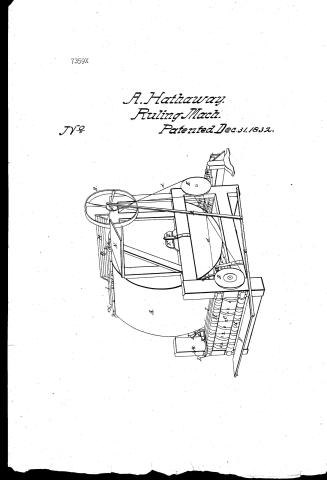 Page 1
-
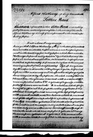 Page 2
-
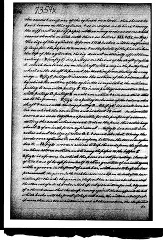 Page 3
-
 Page 4
-
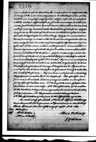 Page 5


U.S. Patent and Trademark Office · Google Patents
Show the transcription Hide (1,651 words)
Machine transcription (LightOnOCR) of the pages as scanned by the USPTO, most of them the handwritten copies made when the records were restored after the 1836 fire. Not checked; it can misread handwriting, so compare it with the scan.
Page 1.
7359X
A. Hathaway.
Ruling Mach.
Patented Dec. 31, 1832.
No 7
Page 2.
Alfred Hathaway, of Troy Massachusetts, Letters Patent.
The schedule referred to in these Letters Patent, and making part of the same, containing a description in the words of the said Alfred Hathaway himself of his improvement in the machine for ruling paper.
To all whom it may concern:
Know ye that I Alfred Hathaway, of Troy in the State of Massachusetts have invented, constituted, & applied to use a new & useful improvement in the machinery for ruling paper which I have named, "Hathaway's improved ruling machine" by which both sides of the paper are ruled at one operation. Said machine is specified and described as follows viz. (reference being had to the annexed drawing as part of this specification) Fig. 1. is a cylinder any 36 inches in diameter with a flange or guide, half an inch high on either end as may suit the operator. This flange or guide serves as a guide to lay the paper on the whole made of bast in 1 turned time; the cylinder is covered with a woolen cloth & runs on friction rollers T.T: a cylinder of larger size would, probably be more convenient. B is a balance wheel, of size & weight sufficient to keep up the motion of cylinder A. B is attached to a shaft which runs across the top of the frame, with a crank on both ends (two balance wheels i.e. one on each end of the shaft would probably be a further improvement) C (in Fig 2) is another cylinder (which should also be of end time if the machine is to be used for ruling on both sides at once, if on one side only wood will answer) covered sufficiently deep to receive the ends which bind the paper to cylinder A. I carry the same from cylinder A. to cylinder C. to be covered also with a woolen cloth, & evenly filed in the cover, so as to bring the
Page 3.
The concave surface of the cylinder on a level. There should be 6 or 8 grooves on this cylinder, & so arranged as to bind & convey the different sizes of paper, with as many cords as grooves, which grooves should match with those on rollers B, X, & E, I. (on fig 1) The size of the cylinder, if from 8 to 10 inches, will be sufficiently large for the paper to turn over; & as the points of the pins stick into the top of the cylinder, the size does not materially affect the execution. D (see fig 1) are pulleys on the ends of the shaft of cylinder C, which run loose on the shaft with a dog in the pulley & each wheel on the shaft to prevent the machine from starting the wrong way. E (fig 1) pulleys to increase the motion of the belt & wheel by which the motion of the cylinder is regulated. The outside pulley to run with pulley B. The inner pulleys are smaller to run with pulleys D. Pulleys B are all connected & run on a stud attached to the frame. F (fig 1) is a pulley on the end of the cylinder shaft & runs with the large pulley B. G, I (fig 1) is a small iron roller on which the end of the cord is about 1/4 inch in diameter, scored as near together as possible, for the purpose of accommodating the cords when moved to clear the pins. This roller hung about 1/8 of an inch from cylinder C. A (fig 1) is a small iron roller about the size of roller C, X, & I, & curved like that, to bring the cords over cylinder C. on the surface, between the grooves in cylinder C. H (fig 1) is iron rollers to keep the cords from the cylinder on their return motion and to convey the paper to the hopper E. E (fig 1) is a frame in which the pins are set for ruling; it consists of two bars of brass from half to three quarters of an inch square, with a groove in the front of each bar, with ends to keep the bars permanent. The groove in the back bar receives a slip on the back of the sizer & the other end of which hooks into the front of the sizer for ink. By means of a thumb screw, the shaft, leaning against the bar opposite the back which hooks into the front of the front bar, the sizer is held fast. If more than one bar or sizer is used at the same time, the shaft should be
Page 4.
he without (i.e. outside of) the books which lock in the groove in the front bar, the latter to raise or depress the fronts of the cisterns in order to bring the points of the pens in the different cisterns to bear with equal pressure on the paper when writing. The boxes or cisterns to contain the ink, are made of brass or copper, about half an inch deep, 8 one one half inch wide (the length in proportion to the number of pens & the manner of their arrangement) with a lip on the top of the back of the cistern to fit in the groove in the back bar of the pen frame & a groove in the front of the cistern to receive the hook on the clasp with tubes (and the front of the cistern extending out from the cistern about half an inch on a straight line with the bottom of cistern; the tubes are flat & stand edge wise about three sixteenths of an inch deep, & open at the top for the purpose of cleaning them. They are made of brass. The pens are flat tubes open at the top, standing edge wise, and are sufficiently wide to fill the ends of the tubes & are and are solaced into them inclining down wards so as to bring the points to bear on the tops of the cylinders while the cisterns have a sufficient distance above the cylinders to give the cords a free operation under them... I the same as I... X (fig 1) is a lever attached to the frame & to give the pressure on the points of the pens & is made fast at one end, having a spring at the other. L is a spring attached to the end of lever X. all is a rack to catch the thing L in, in order to get the pressure on the points of the pens. M (fig 100) is a table for the paper. O (fig 101) treadles which hang at the back parts of the frame. P (fig 102) the foot board which is made fast to the ends of the treadles, & by means of which the machine is worked. Q (fig 103) the fit iron or swing which comes from about the middle of the treadle to the back. R the crank made to vary to accommodate the motion of the foot... T, T, friction rollers. U, iron or brass studs made fast to the sides of the frame and bearing lightly against the ends of the shaft of the cylinder in its place... W, a small iron roller about half the size of the iron rollers T, & moved to match with U to keep the cords as near the cylinder as possible & not touch it in order
Page 5.
7359X
to give the pen a free operation. X, is a pen frame support which is hung at B, and varied by screw e to alter the position of the system as necessity may require. a (fig 1) is for the same purpose with X, but of a different form. f is the top hinge to at X, & is made fast to the frame by a set screw with a slot in the box to admit of moving to accommodate the position of the pen. (fig 2) is a guide on the side of the frame in which one of the tacks operates to keep the foot motion steady. C (fig 3) is a round belt or band (running in order with the cords round cylinder A and round cylinder C, on the surface) sufficiently strained to give cylinder A, the same motion with cylinder C. A round belt or bands by means of which the foot motion is connected with & communicated to the Machine... C (fig 1) is a screw by which the position of the pen is regulated. S (fig 1) is the hopper which receives the paper after it is ruled. Figures 1 are a set of cords running from the small iron rollers A, to cylinder C, to bind the paper to cylinder C, & carry it to cylinder C. Figures 2 are a set of cords to bind the paper to cylinder C, & carry to rollers B on the back of the frame. Figures 3 are a set of cords which carry the paper from rollers B to the hopper S. The specific improvement which I claim as my invention in the aforegoing specification, are. 1st Ruling both sides of paper at one operation, or one side only... 2nd The application of the motion to the Machine, & the general arrangement of the Machine, & the operating of it by one person... 3rd The peculiar construction of the pins. 4th The application of the pens to the tops of the cylinders.
In testimony of which I hereunto set my name at Providence in the State of Rhode Island this twelfth day of Sept. A.D. 1838.
Tomp. Mittrages
Wm. J. Patton
Allen & Brady
Alfred Hathaway
[Lyde Mays]
Published accounts: journal notice
Notice in the monthly list of patents
Journal of the Franklin Institute, new ser., vol. 11 (1833), p. 390 · View the page
49. For an improvement in the Machine for Ruling Paper; Alfred Hathaway, Troy, Bristol county, Massachusetts, December 31.
About this record
- Patentee
- DATAMP
- Date
- the Name and Date index of patents, DATAMP, USPTO records
- Invention
- DATAMP
- Listed in
- the Name and Date index of patents, DATAMP, USPTO records, Jim Shaw's X-patent list, the Journal of the Franklin Institute, Burke's List of Patents (1847)
- Burke's 1847 Patent Office list gives the same patent.