

Drawings and documents
National Archives restored drawings: drawing
J. Atwater's Patent Drawing for a Fire Grate


National Archives, Restored Patent Drawings (Record Group 241) · Full-size scan at the National Archives · Catalog record
Show the text on the drawing Hide (66 words)
Words on the drawing as machine-read by the National Archives; not checked. Useful mainly for searching.
Sheet 1. Ane / Places bas / J. .ATWATER. / 126. STOVES & FURNACES / FIRE GRATE. / [154] Fire Places. / Patented 9th Jan 18BB. / 25. Och 1832 / CLASSIFICATION / Fig 1. / 7367 X / BION. / 8' / 8h / d 85 / Fig 4. / Fig B. / kct / Fig 2. / go
Sheet 2. LASSIFICATION / 7367.4 t / DIVISION. / Hig 8. / Hig I. / of / colo
Sheet 3. CLASSIFICATION / 7367-X / Fif5. / DIVISION / cc / 14. / bb / aa / Fig 7. / Fig 6. / of / 0/90 0 8
USPTO scan
The patent as scanned by the USPTO
-
 Page 1
-
 Page 2
-
 Page 3
-
 Page 4
-
 Page 5
-
 Page 6
-
 Page 7
-
 Page 8


U.S. Patent and Trademark Office · Google Patents
Show the transcription Hide (2,280 words)
Machine transcription (LightOnOCR) of the pages as scanned by the USPTO, most of them the handwritten copies made when the records were restored after the 1836 fire. Not checked; it can misread handwriting, so compare it with the scan.
Page 1.
7367X
J. Atwater.
Fire Place.
Patented Jan. 9, 1833.
2 Sheets Sheet 1
Fig. 5

Fig. 3

Fig. 2

Fig. 1

Fig. 4

Page 2.
2 Sheets. Sheet 2.
7,367 X
J. Stuntz,
The Place.
Patented Jan. 9, 1833
Fig. 5.
Fig. 6.
Fig. 7.
Fig. 9.
Page 3.
Jan 9, 1833
James Alwater
Letters Patent
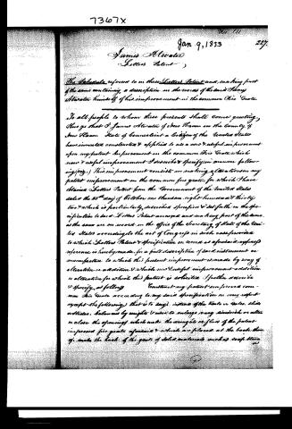
The Schedule referred to in these Letters Patent and making part of the same containing a description in the words of the said James Alwater himself of his improvement in the common Fire Grate.
To all people to whom these presents shall come greeting, Know ye that I James Alwater of New Haven in the County of New Haven State of Connecticut a citizen of the United States have invented constructed & applied to use a new & useful improvement upon my patent improvement in the common Fire Grate which new & useful improvement I describe & specify in manner following (viz.) This improvement consists in making alterations in my patent improvement in the common fire grate, for which I have obtained Letters Patent from the Government of the United States dated the 25th day of October one thousand eight hundred & thirty two & which is particularly described specified & set forth in the specification to said Letters Patent annexed and making part of the same as the same are on record in the office of the Secretary of State of the United States according to the act of Congress in such case provided to which Letters Patent & specification on record as aforesaid express reference is hereby made for a full description of said instrument or manufacture to which this present improvement is made by way of alteration or addition & which new & useful improvement addition or alteration for which this patent is solicited I further describe & specify as following Construct my patent improved common Fire Grate according to my said specification in every respect except the following that is to say instead of the Vents or Vents slide outlets, balance by weights & uses to enlarge or any diminish or alter or close the openings which make the weights or flow of the patent improved fire grate aforesaid & which are placed at the back thereof make the back of the grate of solid materials such as soapstone.
Page 4.
228.
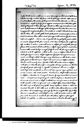
a fire brick or iron with one or more openings in that part of the back which usually incloses the fuel which opening should slope upward & outward from the inside of the grate toward the chamber in the rear at about an angle of forty five degrees measured from the plane of the back of the grate & these openings should in their size correspond with and be proportioned to the size of the whole grate but should not in ordinary grates vary much from two inches in width & should be somewhat shorter than the width of the back of the grate measured from side to side & not more than three such openings will ordinarily be needed or found useful. And in order to regulate the draught of the grate at pleasure so as to assist with the fire or cause it to burn with greater or less intensity, construct a valve or moveable cover or stopper for each of the openings of some solid material which will bear a high degree of heat such as iron or some other metal of large enough fully to cover the opening or orifice to which it is to be applied, which valve, cover or stopper should be attached firmly to a rod or shaft supported by proper bearings at or near each end thereof which bearings may be placed on the back or sides of the grate so that the rod or shaft & the valve cover or stopper attached thereto will readily turn together & thus the valve cover or stopper will open or close the openings or draughts already mentioned in the back part of the grate separately or together at pleasure. The rod or shaft must be of solid material such as will bear a good degree of heat such as iron or some other hard metal. Each rod or shaft & the valve, cover or stopper, attached to it may be turned by any means that are convenient. A useful mode of doing it will be to form a small crank at one end of each rod or shaft & attach one end of a wire or small rod to the crank at the end of each rod or shaft before described & bring the other end to the front part of the grate & place a knob or other convenient handle to this other end so that when the valve cover or stopper closes its corresponding opening by its own weight then by pulling the wire or small rod each shaft or rod with its valve cover or stopper will be made to revolve & open the place, orifice or opening to which it is fitted, or when more convenient a knob or handle may be placed.
Page 5.
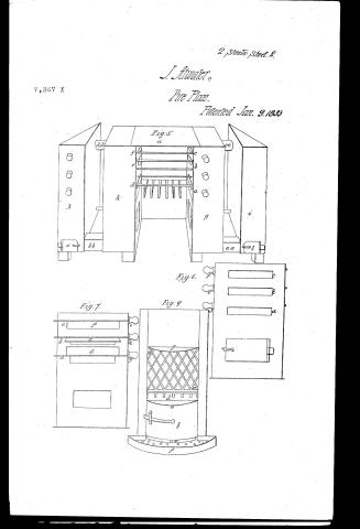
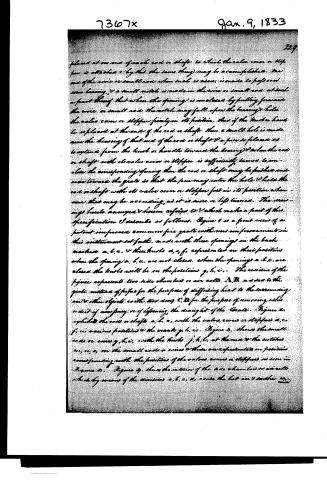
placed at one end of each rod or shaft to which the valve cover or stopper is attached, and by this the same thing may be accomplished. One end of the wire or small rod when such is used is made to pass over some bearing, and a small notch is made in the wire or small rod at such a point thereof that when the opening is unclosed by pulling forward the wire or small rod the notch may fall upon the bearing hole the valve cover or stopper firmly in its position. Thus if the knob or handle is placed at the end of the rod or shaft, then a small hole is made near the bearing of that end of the rod or shaft and a pin is placed as to extend from the knob or handle toward the bearing, and when the rod or shaft with its valve cover or stopper is sufficiently turned to unclose the corresponding opening then the rod or shaft may be pushed and raised toward the grate so that the pin may enter the hole and hold the rod or shaft with its valve cover or stopper fast in its position whenever that may be necessary, as it is more or less turned. The drawings hereto annexed and herein referred to which make a part of this specification I describe as follows. Figure 1 is a front view of a patent improved common fire grate with new improvements in this instrument set forth, made with three openings in the back marked a, b, c, and three knobs d, e, f, represented in their positions when the openings a, b, c are not closed, when the openings a, b, c are closed the knobs will be in the positions g, h, i. The reverse of the figure represents two side chambers or air cells A, B, used to the grate instead of pipes for the purpose of diffusing heat to the surrounding air and other objects with less loss. C, D for the purpose of removing ashes or dirt of necessity or of defending the draught of the grate. Figure 2, exhibits the rods or shafts a, b, c, with the valve covers or stoppers d, e, f, in various positions and the marks g, h, i. Figure 3, shows the small rods or wires g, h, i, with the knobs j, k, l, at the end and the notches m, n, o, on the small rods or wires and there are represented in position corresponding with the positions of the valve covers or stoppers as seen in Figure 2. Figure 4, shows the interior of the side chambers or air cells which by means of the divisions a, b, c, d, cause the hot air to another
Page 6.
7367x Jan. 9, 1833
230.
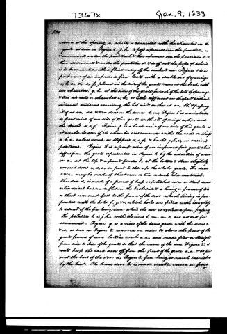
cavities at the opening a, which is connected with the chambers in the grate as seen in Figure 1, f, h, to pass upwards over the partition u downwards under the partition b, then upwards over the partition c, then downwards under the partition d, & so off into the pipe f, which is to be connected with a flue to carry off the smoke & air. Figure 5 is a front view of an improved fire grate with a double set of openings a, b, c, d, e, f, placed in the sides of the grate & one at the back with two chambers, g, h, at the sides of the grate for each of the sets of openings & two air cells or chambers i, k, as little different in shape & without internal divisions receiving the hot air & smoke at aa, bb, & passing it off at cc, dd, & two doors in the same t, m, Figure 6 is an interior or front view of one side of this grate with its openings a, b, c, and the backs d, e, f. Figure 7 is a back view of one side of this grate as it would be seen if its chamber was removed with the rods or shafts a, b, c, valves, covers, or stoppers d, e, f, & knobs g, h, i, in various positions. Figure 8 is a front view of an improved fire grate which differs from the grate represented in Figure 1, by the addition of a cover a, at the top & a pan & fender b, at the bottom & three slightly covered doors c, d, e, in front to close up the whole grate. The doors c, d, e, may be made of sheet iron or tin or such like material. The door d, is made of a frame of half or polished iron or steel semi-cylindrical bars made flat in the back side & a lining or frame of tin or sheet iron made fast to the frame of the door which lining is perforated with the holes f, g, h, which holes are filled with glass to admit of the fire being seen while the air is excluded from passing. The palatines h, i, j, k, with the irons l, m, n, o, are added for ornament. Figure 9 is a view of the same grate with the doors c & d, as seen in Figure 8, removed in order to show the front of the grate formed of iron lattice work a, a, and made flat or straight from side to side of the grate so that the curve of the door Figure 8, d, will keep the said door off from the front of the grate a, a, & so prevent the bars of the door d, Figure 8, from being so much tarnished by the heat. The lower door b, is made double curved in front.
Page 7.
reflet in the oven as splitters at the top of the same at a, a, & at the bottom a place a slide or stopper c, which when pushed back close the space between the front & back of the door at the bottom & when pushed forward opens the same. The use of this is to admit the air which is to feed the fire to pass upward thru the door & out at the top between the front & back plates of the door at c, d, & then pass thru the fuel & ignite the same. The pan f is seen in this figure which is laid by the fender b, in Figure 8. The grate in Figure 6 is represented with a top w, & in Figure 8, with a top a & the grate in Figure 1 may also be used with a top & in Figure 5 & in Figure 1 with a pan or bottom when needed. These drawings exhibit the patent improved common fire grates as altered & claimed in this patent in some of the various positions in which the same may be conveniently used according to the fancy or taste of the owner & as to correspond with the furniture of the open fireplaces on which they are placed. The Figure 9, or 9', is such a piece of sheet iron or other solid substance which in shape is a segment of a circle & is used to prevent the air which comes in from below thru the door b, otherwise from ascending any higher than this part of the grate & causes the air to pass thru the fuel as before mentioned (whether door c, as seen in Fig. 8 is closed or not) & the grate is filled with fuel.
I claim as my improvement that in the place of a slide or slide grate or grates used in my patent improved common fire grate to regulate the draught of the same, I have substituted as many other covers or stoppers as there may be openings in the back or sides of the grate by means of which the draught is regulated at pleasure or entirely closed in the manner set forth on this specification & all the benefits which are set forth in my patent for my improved common fire grate dated 25th October 1832, as resulting from the use of slides or grates are thereby obtained in a more convenient manner than this is all I claim in this patent. In testimony that the above is a true specification of my said improvement as above described I have hereunto set my hand the 17th day of December one thousand eight hundred.
Published accounts: journal notice
Notice in the monthly list of patents, with remarks
Journal of the Franklin Institute, new ser., vol. 12 (1833), p. 20 · View the page
8. For an improvement in the common Fire Grate, as patented on the 25th of October, 1832; James Atwater, New Haven, Connecticut, January 9.
Remarks. The improvements now patented are described at great length, and illustrated by drawings upon five separate sheets. Referring to our notice of the former patent, we will now add an abstract of the new claims. Instead of the slide, or slides, to regulate the draught, there is now substituted as many valves, or covers, as there may be openings in the back or sides of the grate, from which substitution, it is said, all the advantages are derived which the former was designed to secure.
About this record
- Patentee
- DATAMP
- Date
- the Name and Date index of patents, DATAMP, USPTO records
- Invention
- DATAMP
- Listed in
- the Name and Date index of patents, DATAMP, USPTO records, Jim Shaw's X-patent list, the Journal of the Franklin Institute, Burke's List of Patents (1847)
- Burke's 1847 Patent Office list gives the same patent.