

Drawings and documents
National Archives restored drawings: drawing
John B. Maag's Patent Drawing for a Balance

National Archives, Restored Patent Drawings (Record Group 241) · Full-size scan at the National Archives · Catalog record
Show the text on the drawing Hide (61 words)
Words on the drawing as machine-read by the National Archives; not checked. Useful mainly for searching.
JOHN B. MAA / Planfor / $350 / Balance / Patented February 19th 1833 / Card TICATION / 7432-X DIVISION. / Fig.2 / Fig 3 / Fig.4 / Fig 6 / OR / Fig. 5. / OIR / Fig. 1. / two / and / distribution / neight the lenes / h their with total / the / perml / the / GIT / OF / there lower Cress. / brigen / the operation / The / The / together / is
USPTO scan
The patent as scanned by the USPTO
-
 Page 1
-
 Page 2
-
 Page 3
-
 Page 4


U.S. Patent and Trademark Office · Google Patents
Show the transcription Hide (1,130 words)
Machine transcription (LightOnOCR) of the pages as scanned by the USPTO, most of them the handwritten copies made when the records were restored after the 1836 fire. Not checked; it can misread handwriting, so compare it with the scan.
Page 1.
7432X
J. B. MAAG.
Balances.
Patented Feb. 19, 1833.
Fig. 1.
Fig. 2.
Fig. 3.
Fig. 4.
Fig. 5.
Fig. 6.
Page 2.
2/19/1833 7432X
Feb 19, 1833. 13.
John D. Maag, of the City and State of New York.
Letters Patent.
The schedule referred to in these Letters Patent and making part of the same containing a description in the words of the said John Maag, Maag himself of his improvement in the Balance.
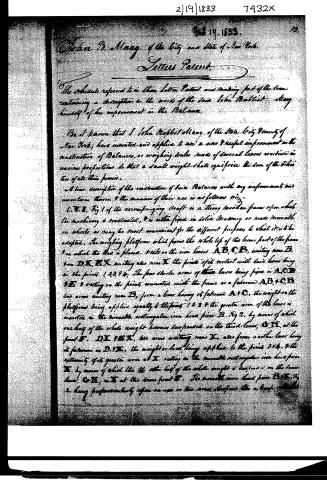
Be it known that I, John Maag, of the State, City, County of New York, have invented and applied to use a new & useful improvement in the construction of Balances, or weighing scales made of several levers combined in various proportions so that a small weight shall equiforce the sum of the other ties of all their forces.
A true description of the construction of said Balances with any improvements and inventions therein & the manner of their use is as follows viz:
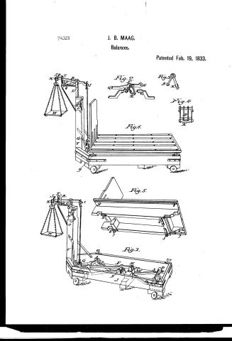
O.V.I. Fig 1 of the accompanying draft is a strong wooden frame upon which the machinery is constructed, & is either fixed in solid masonry or made moveable on wheels as may be most convenient for the different purposes to which it is to be adapted. The weighing platform which forms the whole top of the lower part of the frame & on which the load is placed rests on the iron levers A.B.C.B, uniting near B, near D.X, E.X, uniting also near X the points of its contact with said levers being at the points 1,2,3,4,5. The four shorter arms of these levers being fixed in A.C.D & E & resting on the points connected with the frame as a fulcrum A.B.+C.B, two arms uniting near B, form a lever having its fulcrum A+C, the weight on the platform being applied equally to the points 1+2 & the greater arm of the lever is inserted in the moveable rectangular iron head piece B. Fig 2, by means of which one half of the whole weight becomes suspended on the third lever, G.H, at the point X. D.X. F.E.X, two arms uniting near X, also form another lever having its fulcrum in D.F.X, the weight or load being applied to the points 3+4, & the extremity of its greater arm at X, resting in the moveable rectangular iron head piece H, by means of which the other half of the whole weight is suspended on the same lever, G.H, in H at the same point X. The moveable iron head piece B.H. Fig 2, being proportionately open on one or two arms, therefore the a knife
Page 3.
7432x
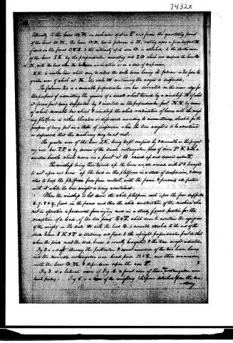
laterally to the lever G, H, an end piece of iron P and forms the gravitating point of the lever G, H, the lever G, H, has its fulcrum in H, resting upon a firm support fixed in the frame O, T, J. & the extremity of its arm G, is attached to the shorter arm of the lever I, K, by the perpendicular connecting rod I, O, which not supports the lever G, H, with the load when the balances are in action or in a state of suspension,
I, K, is another lever which may be called the scale beam having its fulcrum in I, from the greater arm of which at K, the scale W containing the weights is suspended,
The fulcrum I, is a movable perpendicular iron bar serrated on the inner edge for the purpose of admitting the grooves of a small wheel turned by a windlass M of which it forms part being supported by & inserted in the perpendicular foot, N, N, by means of which movable bar wheel & windlass the whole combination of levers with the weighing platform is either elevated or depressed according to circumstances, elevated for the purpose of being put in a state of suspension when the true weight is to be ascertained or depressed that the machinery may be at rest.
The greater arm of the lever I, K, being kept confined by & movable in the projecting iron bar I, P, is by means of the small rectangular piece of iron P, R, with a wooden handle which moves on a pivot at Q, raised up and secured under it.
The windlass being then turned up the levers are all raised with it & brought to act upon and bear up the load on the platform in a state of suspension, & doing also to keep the platform free from contact, with the frame & prevents all friction with it while the true weight is being ascertained.
When the windlass is let down the whole platform rests upon the four supports b, j, s & q, fixed in the frame and then the whole construction of the machine when not in operation is preserved from injury and in a steady fixed position for the reception of a load, of the two points S & T, which serve to ascertain the equilibrium of the weights in the scale W with the load G, is movable attached to the end of the scale beam I, K & T is stationary and fixed to the upright perpendicular foot so that when the points meet the scale beam is exactly horizontal & the true weight indicated.
Fig 2 is a draft showing the particular & exact insertion of the two levers being into the movable rectangular iron head piece B & X, and their connection, with the lever G, H, & dependence upon the axis P,
Fig 3, is a lateral view of Fig 4 a front view of their rectangular iron head pieces. Fig 5 is a view of the weighing platform detached from the two.
Page 4.
and showing also the point by which it rests upon the lower lever.
Fig. 6. is a view of the machine at rest. That which is specially claimed as a new invention & improvement are the disposition & distribution of the whole weight equal upon the four lower levers so as to unite their powers with the total weight at the point F' of the lever G, H, together with the construction, position & combination of these lower levers.
Also the construction, position & operation of the movable serrated iron bar forming a fulcrum for the scale beam, together with the windlass & wheels connected therewith by which the whole scale and platform are acted upon & suspended in equilibrium.
Witness:
Samuel H. Taylor
John A. Taylor
John Pottier & Mary
(For in patent folio) 1278 no. 25
C. to
CLYMC.
Published accounts: journal notice
Notice in the monthly list of patents, with remarks
Journal of the Franklin Institute, new ser., vol. 12 (1833), p. 96 · View the page
29. For a Balance or Weigh Scales; John Baptiste Maag, city of New York; an alien who has declared his intention to become a citizen of the United States. February 19.
Remarks. This machine is the well know instrument for weighing wagons, &c. with their loads, and although there is a distinct claim made, we do not think that the main point which is relied upon is novel in its character. There are four levers under the platform, upon which it, with the load upon it, bears, their united action being on a fifth lever which leads to the rod operating on the scale beam; and the claim is to " the disposition and distribution of the whole weight equally upon the four lower levers, so as to unite their powers with the total weight," in a point on the fifth lever, "together with the construction, position, and combination of the lower levers." The scale beam, or balance, has its fulcrum supported upon a rod which descends into a vertical post, and has teeth on one side of it, forming it into a rack, there being a pinion by which it can be lowered or raised, in the manner of many of the finer kind of scales. The rack is in the specification called a "serrated iron bar," and the crank and pinion are denominated the windlass and wheel; and the use of them is claimed as new. We are not able to discover any thing in this apparatus rendering it superior, either in accuracy, convenience, or simplicity, to such weighing machines as are already in use.
About this record
- Patentee
- DATAMP
- Date
- DATAMP, USPTO records
- Invention
- DATAMP
- Listed in
- the Name and Date index of patents, DATAMP, USPTO records, Jim Shaw's X-patent list, the Journal of the Franklin Institute, Burke's List of Patents (1847)
- The sources give different dates; the date shown is the one most of them agree on.
- The Franklin Institute's journal confirms the date shown.
- Burke's 1847 Patent Office list gives the same patent.