

Drawings and documents
National Archives restored drawings: drawing
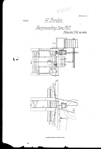
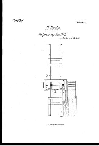
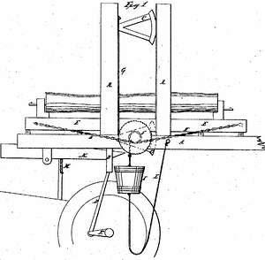
Henry Gordon's Patent Drawing for a Saw Mill


National Archives, Restored Patent Drawings (Record Group 241) · Full-size scan at the National Archives · Catalog record
Show the text on the drawing Hide (127 words)
Words on the drawing as machine-read by the National Archives; not checked. Useful mainly for searching.
Sheet 1. $4- / 110. SAWS. / 143, WOOD SAWINE / [130] Reciprocating Saw Mills / Henry Gordon / Tol.lb.p.7/. / SAWING MA Mikala / Reciprocating Saw: / law- law-mill, mill, / CLASSIFICATION / 74534 / DIV ISION. / Fight. / Fif.2. / References, / Fid.1. side view, / Fir 2. front " Fig 3 toporen / A.A frame, Bsaw gate, / GT / C. vibra ling arms, / D. pitman E. carriage. / F. rag wheel G.feeder, / Holain, I.bucket to drawback carriage, / trough to fill bucket. / I. cord attached to bucket. / M. cord to canttrough attached tegate. / FI / 11 / Patent Office / Deefg. 1841 / Made under the direction of the Commipion of Patients / in conformity with Oct of Congreps 3 March 1837 / MLCunoth / Commisionely Patuty
Sheet 2. 110. SAWS. / [130] Reciprocating Saw Mills / CLASSI / ICATION / 7453ex / DIV ISION. / F' / Fifes, / OIR
USPTO scan
The patent as scanned by the USPTO
-
 Page 1
-
 Page 2
-
 Page 3
-
 Page 4
-
 Page 5


U.S. Patent and Trademark Office · Google Patents
Show the transcription Hide (957 words)
Machine transcription (LightOnOCR) of the pages as scanned by the USPTO, most of them the handwritten copies made when the records were restored after the 1836 fire. Not checked; it can misread handwriting, so compare it with the scan.
Page 1.
7453X
H. Gordon,
Reciprocating Saw Mill.
Patented Feb. 28, 1833.
2 Sheets. Sheet 1.

AM. PHOTO-LITHO. CO. N.Y. (OSBORNE'S PROCESS)
Page 2.
7453 Y
2 Sheets—Sheet 2.
H. Gordon,
Reciprocating Saw-Mill.
Patented Feb. 28, 1833.

A.M. PHOTO-LITHO. CO. N.Y. (OSBORNE'S PROCESS)
Page 3.
X7453
Feb 28, 1833
Henry Gordon, of Liberty Township, Pennsylvania
Letters Patent
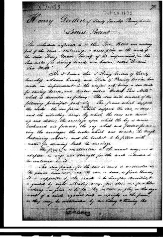
The schedule referred to in these Letters Patent and making part of the same, containing a description in the words of the said Henry Gordon himself of his improvement in the saw mills for sawing boards and timber, called "Gordon's Saw Mill."
Be it known that I Henry Gordon of Liberty Township a County and State of Pennsylvania, have made an improvement in the useful art, being a saw mill for sawing boards and timber called "Gordon's Saw Mill" which is described as follows. This saw mill consists of the following principal parts viz: The frame which supports the works; the saw frame which supports the saw, or saws; and the vibrating arm, by which the saws are moved up and down; the carriage upon which the log is moved backward and forward; the log wheel and fender for moving the carriage; the water wheel and cranks; the trough containing water; and the bucket to be filled with water for drawing back the carriage.
The frame is constructed in the usual way, and is adapted in size and strength for the work intended to be contained in it.
The saw frame, for the saw or saws is constructed in the usual manner, and the saw, or saws, is fixed therein. It is supported by the cranks to be hereafter described, & is guided by eight vibrating arms, four above and four below working on joints or hinges. They vibrate or play on the movement of a circle against posts or uprights in the frame, as they may be constructed by mortising & tenoning the
[Signature]
Page 4.
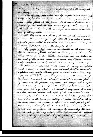
rocking or vibrating arms into a crop bar, or into the sides of the saw frame.
The carriage upon which the log is placed and moves backwards and forwards, is made in the usual way, and moves upon rollers fixed in the frame. It is moved backwards and forwards by the winding and unwinding of a chain or cord attached to each end of the carriage and wound round the axle of the sag wheel.
The Rag wheel and Feeder, for moving the carriage in, move in the usual way, except that the rag wheel is double and the feeder which is attached to the saw frame, and a feed is made to feed only when the saw goes down.
The water wheel may be constructed in the usual way like a common flatter wheel, or it may be a chain water wheel turning on two rollers, one above and one below, on the axle of the water wheel is a crank and Pitman attached to the saw frame, and by which it is moved up and down.
The pitman is attached to the frame, by having a cross piece with a screw on each end and an axle point or segment of a circle upon which the saw gate or frame works. Iron straps pass from the aforementioned cross piece over the lower bar of the frame to a small bar above it, where it is screwed fast by nuts and the pitman adjusted, and trough which is filled with water by a spout from the water is placed on an axle near the rag wheel, and bucket is suspended by a rope or chain wound round the axle of the rag-wheel under the trough, and cord is attached to the bottom of this bucket and a pin in the frame for catching it when the cut in the log has been given, the trough is upset by a string from the gate of the mill, which fills the bucket below, and causes it to descend and carry back the carriage by unwinding the cord on the axle of the rag wheel, when the bucket has returned to a depth equal to the length of the log, it is then—
Page 5.
X 7463
Effect by the cord attached to the bottom and the before-mentioned pin.
Operation, the log being prepared is fastened on the carriage in the usual way, the water wheel being put in motion, giving motion to the crank and pitman on its yoke gear, the pitman moves the frame and saw up and down to cut the log, at the same time the motion of the saw downwardly works the faster and sag wheel, which moves the carriage and log by the cord attached to the carriage, being wound on the axle of the sag wheel, the gate is shut in the usual way by that pitman, the carriage and the carriage is brought back as before described, by the vibrating trough and ascending bucket of water.
The invention here claimed and desired to be secured by Letters Patent, is the before described Saw Mills, particularly the mode in which the saw frame is hung; the vibrating or rocking arm; and the mode in which the carriage is moved backward and forward.
For a further illustration of my invention I refer to the model and drawing of the same deposited in the Patent Office.
In testimony whereof I have subscribed my name before two witnesses this 20th day of February 1833.
Witnesses:
Chas. M. Keller
Wm. P. Elliott
Henry Gordon
80
Published accounts: journal notice
Notice in the monthly list of patents, with remarks
Journal of the Franklin Institute, new ser., vol. 12 (1833), p. 104 · View the page
48. For an improvement in the Saw Mill; Henry Gordon, Liberty, Adams county, Pennsylvania, February 28.
Remarks. The saw frame instead of working between fender posts is to be suspended by vibrating arms, four above and four below, one half of them attached to the back, and the other to the sides of the frame. These must have segments of circles at one of the ends of each bar, or at least to those at the sides of the frame, or they must be attached to a second vibrating bar; the mode of attachment, however, is described in very general terms. The log is to be drawn back by the weight of a bucket to be filled with water, and tilted when it has descended. Some other novelties are mentioned, but none of them appear to be worthy of particular notice. The hanging of saw frames upon vibrating bars, in different ways has been patented more than once; it, however, does not appear to offer any advantage over well constructed slides, or fender posts.
DATAMP: illustration
Illustrations from DATAMP

DATAMP (Directory of American Tool and Machinery Patents), via the Internet Archive · Archived DATAMP page
About this record
- Patentee
- DATAMP
- Date
- the Name and Date index of patents, DATAMP, USPTO records
- Invention
- DATAMP
- Listed in
- the Name and Date index of patents, DATAMP, USPTO records, Jim Shaw's X-patent list, the Journal of the Franklin Institute, Burke's List of Patents (1847)
- Burke's 1847 Patent Office list gives the same patent.