

Drawings and documents
National Archives restored drawings: drawing
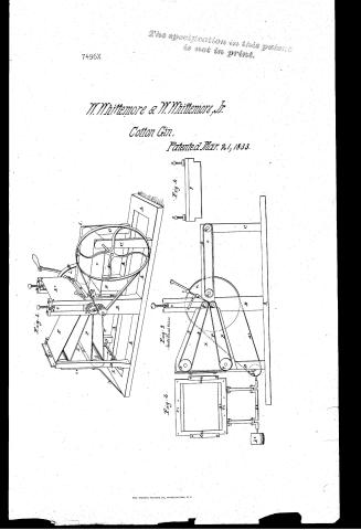
W. Whittenmore and W. Whittenmore, Jr.'s Patent Drawing for a Roller Gin

National Archives, Restored Patent Drawings (Record Group 241) · Full-size scan at the National Archives · Catalog record
Show the text on the drawing Hide (51 words)
Words on the drawing as machine-read by the National Archives; not checked. Useful mainly for searching.
botton gins / 12 agr. produce ets / W. WHITTEM ORE $W.WHITTEMORE JRS / 13. BRAKES & GINS. / ROLLER GIN . / Roller Gins. / Patented March 2/4/833 / Fig.1. / CLASSIFICATION / 4496-x X / DIVISION. / Fig 3 / Fig 2 / Flg. 4 / f282 / E2 12 / 10 / E2 / me millers / d2 / 62 / b2
USPTO scan
The patent as scanned by the USPTO
-
 Page 1
-
 Page 2
-
 Page 3
-
 Page 4
-
 Page 5
-
 Page 6
-
 Page 7
-
 Page 8


U.S. Patent and Trademark Office · Google Patents
Show the transcription Hide (2,693 words)
Machine transcription (LightOnOCR) of the pages as scanned by the USPTO, most of them the handwritten copies made when the records were restored after the 1836 fire. Not checked; it can misread handwriting, so compare it with the scan.
Page 1.
7496X
The specification in this patent is not in print.
W. Whittemore & W. Whittemore, Jr.
Cotton Gin.
Patented Mar. 21, 1833.

THE NORRIS PETERS CO., WASHINGTON, D.C.
Page 2.
7496X
March 21, 1833
William Whittemore & William Whittemore Jr.
Letting Patent
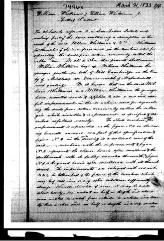
The Schedule refers to in these Letters Patent, and making part of the same, containing a description in the words of the said William Whittemore & Wm. Whittemore for themselves of their improvement in the machine used for separating the seeds from cotton commonly called the roller gin. To all to whom these presents shall come:
William Whittemore Esq. & William Whittemore the younger gentleman both of West Cambridge in the County of Middlesex & Commonwealth of Massachusetts send greeting.
Be it known that we the said William Whittemore and William Whittemore the younger have invented made & applied to use a new and useful improvement in the machine used for separating the seeds from cotton commonly called the roller gin which invention & improvement is specified & described as follows namely: The whole machine with the improvement is represented in the figure 1st in the accompanying hereto annexed as a part of this specification & figure 2d in the drawing is a sectional view of the said machine, with the improvements & figure 3d represents the clearer herein after mentioned & the double crank with its pulley connected therewith & figure 4th is the guard herein after mentioned with its thumb screws. The improvements are colored with red ink.
AA is the bottom part of the frame of the machine which may be of cast iron or any other substance sufficiently strong. When constructed of iron it may be made about twenty six inches & an half in length and about nine inches in width from outside to outside and from by three inches and an half in length and six inches
Page 3.
March 21, 1833
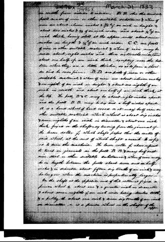
in width from inside to inside. B.B. are the middle posts made of iron or other suitable substance & when of iron are about eleven inches & 7/8" of an inch in height & about two inches & 3/4 of an inch wide, and about 3/4 of an inch thick, having slots at the upper ends about nine inches in length & 3/4 of an inch wide. C.C. are parts of iron or other suitable material & when of iron may be made about eight inches and three sixteenths wide, and about one half of an inch thick, excepting near the bottom where they are a little thicker, so as to form a shoulder and be more firm. D.D. are parts of iron or other suitable material, & when of iron are about eleven inches & one eighth of an inch in height & about one eighth of an inch in width, and about one half of an inch thick at the top. The posts B & C may be about eight inches apart and the posts B.B. may be six and a half inches apart.
A is a hand wheel of hard wood or it may be of iron or other suitable material which wheel is about six inches & seven eighths of an inch in diameter & about one inch thick, fixed on the shaft, extending from the journal of the lower roller f, which shaft passes thru the centre of said wheel, at the end of which shaft a crank E is fixed to turn the machine. The lower roller f, above referred to turns in journals in the posts B.B. & may be of cast iron, steel or other suitable substance, & when of iron may be in length between the posts about seven and one half inches & in diameter about fifteen six tenths of an inch & may be longer when the machine is proportionally larger.
On the shaft at the opposite end of this roller is fixed a pinion wheel G about one & a quarter inches in diameter & about seven eighths of an inch wide having twelve teeth, & a pulley H about one inch & seven six tenths of an inch in diameter. J is a pinion wheel on the shaft of the upper
Page 4.
7946x 7496Y March 21, 1833
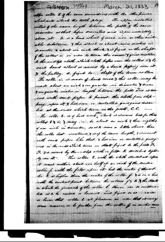
upper roller S, of the same dimensions with the other pinion wheel parts which the teeth play. The upper metallic rollers of the same length between the posts, of the same diameter as that before described and is immediately above it. It is a bone wheel of wood, iron or other suitable substance, and this wheel is about nine inches in diameter and about one inch thick, and is fixed on the shaft of the roller i, in order to turn the same and give motion to the endless cloth which cloth passes over the roller i, and said band wheel is moved by a hand passing over it and the pulley d, fixed to the shaft of the lower roller. The roller i, is made of hard wood and this roller may be made about an inch and one quarter in diameter and seven and one quarter inches in length between the posts and is covered with sand paper to prevent the cloth from slipping upon it, and has iron or metallic guide-gears inserted at the ends which turn in the posts C, C.
The roller t, is of hard wood, which is deemed best for this roller t, is, and may be about an inch and three eighths of an inch in diameter, so as to move a little slower than the roller last mentioned, and is of the same length, and covered with sand paper like that, and has iron or metallic guide-gears in the ends which turn in stands fixed to the posts B, B, and is moved by the endless cloth or felt K stretched tightly over it. This roller t, with the cloth stretched upon it comes within about one half of an inch of the under roller f, with the felt upon it, but the centre of the roller t, is higher than the centre of the roller f, and is on a line with the central point between the rollers f, S, and the stands in which the journals of the roller t, turn, are so constructed as to be raised or lowered and fixed so as to raise or lower that roller t, at pleasure, in order that it may come nearer, or be further from the roller f, in such manner...
Page 5.
March 21, 1833
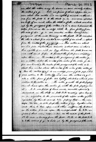
...so that the cotton may be drawn in more readily between the rollers f & g. O.O. are pieces of sheet copper, tin, or iron about two inches and one eighth of an inch on the inside from the parts C. to the studs n. n. and some of about one half of an inch above the cloth or felt, which are held up by the grooves of the rollers, i & l, & serve to prevent the cotton placed on the endless cloth K. from falling from the side of it. q & r. are wooden rollers having iron guageons at the ends turning on the posts D.D. one above the other & about five inches & one eighth of an inch apart from the centers of the guageons. These rollers are about one and five sixteenths in diameter & about seven inches & three eighths of an inch in long between the parts & are covered with sand paper to prevent the felt from slipping upon them. The centers of the guageons of the roller q. are a little below the center of the roller of the roller f. before mentioned, the center of the guageons of the roller r. is about three inches above the center of the roller of the roller q. Over the rollers p & f is an endless piece of felt for which gives motion to the roller p and over the rollers n & q is also a like piece of felt. S.S. lightly stretched which gives motion to the roller n. The roller q with the felt passing over it bears upon the roller f, with the felt passing over it. t. t. are pieces of hard wood, movable upward & downward in the slots in posts B.B. & resting upon boys u. u. adjusted to the journals of the upper roller q and regulated by thumb screws N.N. passing through the iron caps W.W. so as to press the rollers p & g together and cause them to bear upon each other sufficiently to draw in the cotton placed upon the endless cloth K. X.X. are pieces of sheet iron, copper or tin on the inside of the posts D.D. and extending from the posts D.D. to the posts B.B. & to the rollers f & g & held up by the guageons of the roller
Page 6.
March 21, 1833
of which pass through the pieces of sheet copper, iron or tin, some above and some below the middle felt B.B. & p.p., which serve to prevent the cotton from falling from the sides of the felt. G is a guard (made of cast steel, about seven & seven eighths inches long & one & seven eighths of an inch wide & one fourth of an inch thick) its top edge tapering down to about one sixteenth of an inch & rounded & polished at the edge, so as not to cut or tear the staple of the cotton.
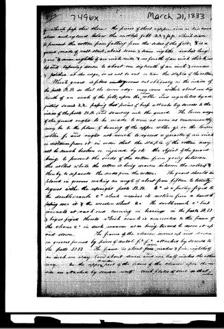
Which guard is fitted on grooves cut obliquely in the inside of the posts B.B. so that the lower edge may come within about one sixteenth of an inch of the felt, upon the roller and regulated by adjusting screws 2.2. passing through pieces of brass attached by screws to the inside of the posts B.B. (and screwing into the guard. The lower edge of the guard ought to be made to come as near as conveniently may be to the place of bearing of the upper roller g, on the lower roller f, and ought not much to exceed a quarter of an inch in distance from it in order that the staple of the cotton may not be much broken or injured by it. The object of the guard being to prevent the seeds of the cotton from going between the rollers while the cotton is being drawn between the rollers & thereby to separate the seeds from the cotton. The guard should be placed in grooves making an angle of about from fifteen to twenty degrees with the upright posts B.B. b' is a pulley fixed to the double crank c' which receives its motion from a band passing over it & the wooden wheel a. The double crank c' has journals at each end turning in bearings in the posts D.D. & boxes fixed thereto which crank is connected to the frame of the cleaner c' in such manner as on being turned to move it up and down.
The frame of the cleaner moves up and down in grooves formed by pieces of metal f.f. attached by screws to the posts D.D. The frame is about four inches & five eighths of an inch one way (and about seven and one half inches the other way. On the upper part of the frame of the cleaner upon the inside are attached by screws metal comb plates of steel so that when
Page 7.
March 21, 1833
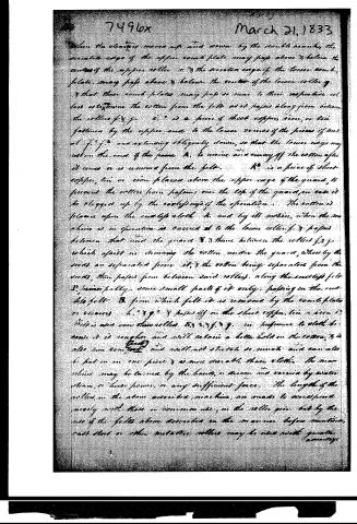
When the elevator moves up and down by the double motion, the serrated edge of the upper comb plate may pass above & below the center of the upper roller, or the serrated edge of the lower comb plate may pass above & below the center of the lower roller, or that these comb plates may pass so near to their respective rollers as to drive the cotton from the felt as it passes along from between the rollers f & g.
i. is a piece of sheet copper, iron, or tin fastened by the upper end to the lower surface of the piece of metal f. extending obliquely down, so that the lower edge may rest on the end of the frame A, to receive and convey off the cotton after it comes or is removed from the felt.
K. is a piece of sheet copper, tin, or iron placed above the upper edge of the guard, to prevent the cotton from passing over the top of the guard, in case it be clogged up by the careless use of the operation.
The cotton is placed upon the endless cloth h, and by its motion, when the machine is in operation, is carried to the lower roller f, & passes between that and the guard K, & thence between the rollers f & g, which assist in drawing the cotton under the guard, where by the seeds are separated from it, & the cotton being separated from the seeds, then passes from between said rollers, along the endless felt D, principally, some small parts of it only, passing on the endless felt D, from which felt it is removed by the comb plates or cleaners h. & g. & passes off on the sheet copper, tin, or iron i.
This is used over the rollers B, R, & f. & g. in preference to cloth because it is rougher and will retain a better hold on the cotton, & is also more compact and will not stretch so much and can also be put on in one piece & is more durable than cloth. The machine may be turned by the hand, or driven and carried by water steam, or horse power, or any sufficient force.
The length of the rollers, in the above described machine, are made to correspond nearly with those in common use, in the roller gin, but by the use of the felts above described in the manner before mentioned, cast shot or other metallic rollers may be used with great advantage.
Page 8.
advantage, without being much firmer, stronger, & less liable to spring than those of wood, may be made much longer than those in common use, & on this account will be preferable. The felt need also better to draw in the cotton than the rollers alone, & to carry itself from between the rollers after it has passed there so that the rollers may not be clogged therewith as happens sometimes in the common roller gear. The cleaner is designed to remove the cotton from these felts after it has passed there & been carried from the rollers & to prevent its passing round on the felts & coming again to the rollers to clog them. The effect of the guard is as before mentioned to prevent the seed from coming to the rollers when they bear upon each other as in the common roller gear and thereby more effectually to prevent them from passing through these rollers. It is to be understood that we do not claim the rollers, frame, screws, wheels, copper, tin & iron plate, pulleys or anything heretofore in common use for the purposes aforesaid, & that what we hereby claim & all to which we claim as new and as our invention & improvement is the guard, felts, & cleaner above described when used in the manner and for the purposes aforesaid & the use thereof in the manner and for the purposes aforesaid. In testimony whereof we have hereunto set our hands this tenth day of March in the year of our Lord eighteen hundred and thirty-three.
Witness
Augustus H. Fisher
B'g'nd.
William Whittemore
William Whittemore Jr.
(2664 words)
Granted March 21, 1833
See on back folio
Reversed & Rejected June 25, 1834.
Published accounts: journal notice
Notice in the monthly list of patents, with remarks
Journal of the Franklin Institute, new ser., vol. 12 (1833), p. 183 · View the page
41. For an improvement in the Roller Gin for Ginning Cotton; William Whittemore, senr., and William Whittemore, jr., West Cambridge, Middlesex county, Massachusetts, March 21.
Remarks. A very minute description of the roller gin is given in the specification, which refers throughout to perspective and sectional drawings. The parts which are claimed as new are plainly designated, and consist of "the guard, felts, and clearer." The guard is a piece of cast steel, which works upon two arms in the frame of the ginning rollers, its lower edge, which is to be about one-sixteenth of an inch thick, smooth, and rounded, drops nearly into contact with the felt or the lower roller. The object of this is effectually to prevent the seeds of cotton from being drawn in with the staple between the rollers. The felts are endless aprons of leather, which are substituted for cloth, as possessing many properties which render it superior to the latter article. Of these felts there are three, with their appropriate rollers; one of these is the feeding apron; the other two receive the cotton and carry it along from the ginning rollers, round which they pass. The upper apron inclines upward, and the lower apron downward; a part of the cotton adheres to the upper felt, but the larger portion of it to the lower one. The clearer is a frame worked up and down by a double crank shaft, having two combs attached to it, like those of the common carding machine, and serving, in a similar way, to remove the ginned cotton from the felts.
About this record
- Patentee
- DATAMP
- Date
- the Name and Date index of patents, DATAMP, USPTO records
- Invention
- DATAMP
- Listed in
- the Name and Date index of patents, DATAMP, USPTO records, Jim Shaw's X-patent list, the Journal of the Franklin Institute, Burke's List of Patents (1847)
- Burke's 1847 Patent Office list gives the same patent.