

Drawings and documents
National Archives restored drawings: drawing
G. W. Potter's Patent Drawing for a Mode of Manufacturing Leaden Pipe

National Archives, Restored Patent Drawings (Record Group 241) · Full-size scan at the National Archives · Catalog record
Show the text on the drawing Hide (82 words)
Words on the drawing as machine-read by the National Archives; not checked. Useful mainly for searching.
207 / W Potter's mode / CLASSIFICATION / 4.498.x / of Manufacturing leaden spepes / DIVISION. / Datented March 23. 1833.X / I, shaft References (and CrauM to which the / hower is applied / Li / II Cords and weights to raise the Pistory. / II. Camo on the shaft to freeps the / Sistous down / M. Valves (represented by dotted lines) / N. Rod of iron in the centre of / - tube / May / NO / Cofued from patent april 18. 1845
USPTO scan
The patent as scanned by the USPTO
-
 Page 1
-
 Page 2
-
 Page 3
-
 Page 4


U.S. Patent and Trademark Office · Google Patents
Show the transcription Hide (802 words)
Machine transcription (LightOnOCR) of the pages as scanned by the USPTO, most of them the handwritten copies made when the records were restored after the 1836 fire. Not checked; it can misread handwriting, so compare it with the scan.
Page 1.
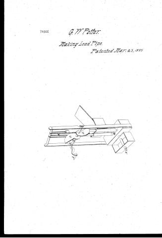
7498X
G. W. Potter.
Making Lead Pipe.
Patented Mar. 23, 1855.

Page 2.
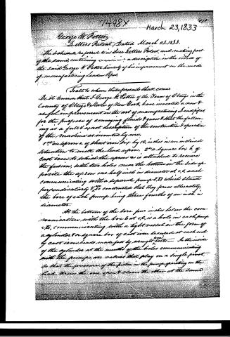
7448X March 23, 1833
George H. Potter
Letters Patent Dated March 23, 1833.
The Schedule referred to in said Letters Patent, and making part of the same, containing a description in the words of the said George H. Potter himself of his improvement in the mode of manufacturing Lead Pipes.
To all to whom these presents shall come.
Be it known that I, George H. Potter of the Town of Otego in the County of Otego & State of New York, have invented a new & useful improvement in the art of manufacturing Lead pipes for the purpose of conveying fluids & gases & that the following is a full & exact description of the construction & operation of the machine as invented by me.
1st an apron a of sheet iron 6 by 12 inches in an inclined situation to melt the lead upon. 2nd a square box b, of cast iron to which the apron a is attached to receive the fusion, with two holes near the bottom on the side opposite the apron one half inch in diameter at c, c, each communicating with a separate pump J, D, which stand perpendicularly & so constructed that they press alternately; the bore of each pump being three fourths of an inch in diameter.
At the bottom of the bore four inches below the communication with the box b at c, c, is a hole in each pump c, c, communicating with a tight vessel in the form of a cylinder or square box of cast iron secured at each end by cast iron heads made fast by wrought iron bolts. In the inside of the cylinder at the mouths of the holes communicating with the pumps, are valves that play on a single pivot, so that the pressure of the piston in the pumps, operating on the lead, throws the one open & closes the other at the same
Page 3.
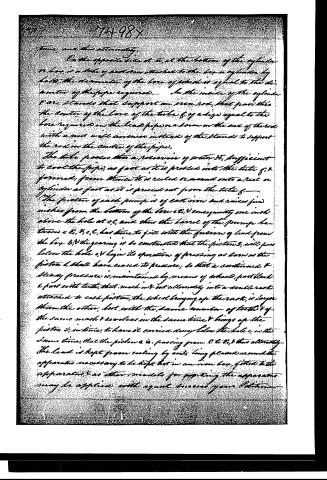
On the opposite side of E, at the bottom of the cylinder or box, is a tube of cast iron attached to the box or cylinder by bolts, the diameter of the bore of which is equal to the diameter of the pipe required. In the inside of the cylinder are stands that support an iron rod, that passes into the center of the bore of the tube 8, of a size equal to the bore required in the lead pipe, or a horn on the end of the rod with a nut will answer instead of the stands to support the rod in the center of the pipe.
The tube passes into a reservoir of water H, sufficient to cool the pipe, as fast as it is pressed into the tube 8, & formed; from thence it is reeled or wound onto a reel or cylinder as fast as it is pressed out from the tube 8.
The piston of each pump is of cast iron and raises five inches from the bottom of the box at E, & consequently one inch above the hole at C, and thus the barrel of the pumps between E, & C, has time to fill with the fusion of lead from the box B, & the gearing is so constructed that the pistons 3, will pass below the hole C, & begin its operation of pressing as soon as the piston 1, shall have ceased its pressure; so that a continued & steady pressure is maintained by means of wheels, part blank & part with teeth, that mesh not but ultimately into a double rack attached to each piston, the wheel bringing up the rack, is larger than the other, but with the same number of teeth & of the same mesh & revolves in the same time & brings up the piston 3, in time, to have it carried down below the hole C, in the same time, that the piston 1, is passing from C to E, & thus ultimately.
The lead is kept from cooling by coils being placed around the apparatus necessary to be kept hot in an iron box, fitted to the apparatus, & as other models for packing the apparatus may be applied with equal success your Patience
Page 4.
claims most particularly the mode of pressing or receiving the fused lead into a tube around a rod, & cooling it in its passage, this the tube in the manner before described, & thus forming the pipe. Dated at Glasgow 24 July 1858.
Geo. M. Potter
Witness
Samuel Whitman
William Babcock
Received & Recorded anew 5 April 1855
900 words
Drawing
Exp'd
1884
Published accounts: journal notice
Notice in the monthly list of patents, with remarks
Journal of the Franklin Institute, new ser., vol. 12 (1833), p. 185 · View the page
45. For a Mode of Manufacturing Leaden Piples; George W. Potter, Otsego, Otsego county, New York, March 23.
Remarks. The apparatus which is the subject of this patent is intended to cast lead pipes of any required length, without the necessity of soldering separate pieces together. The cast iron tube which forms the mould for the pipe is placed horizontally, and passes through a cast iron box which is to be supplied with cold water. The back end of this tube extends through VOL. XII.-No. 3.- SEPTEMBER, 1833. 24 the water box, into another which is a receptable for melted lead. A core, the size of the bore of the tube, extends through it and into the reservoir, where it is supported by one end, without the necessity of any thing to sustain it, either within, or at the mouth of the tube. Above the cast iron reservoir of lead, there are two force pumps of iron, the pistons of which are made to operate alternately. When one of the pistons is raised, melted lead runs into the barrel, from a trough supplied for that purpose. At the bottom of each pump barrel there is a suitable valve, to prevent the return of the lead. When the apparatus is used, it must, in all the parts containing fused lead, be surrounded by burning coals, so as to keep the metal in that state. The claim is to "the pressing, or receiving the fused lead into a tube, around a rod, and cooling it in its passage through the tube, in the manner before described, and thus forming the pipe."
About this record
- Patentee
- DATAMP
- Date
- the Name and Date index of patents, DATAMP, USPTO records
- Invention
- DATAMP
- Listed in
- the Name and Date index of patents, DATAMP, USPTO records, Jim Shaw's X-patent list, the Journal of the Franklin Institute, Burke's List of Patents (1847)
- Burke's 1847 Patent Office list gives the same patent.