

Drawings and documents
National Archives restored drawings: drawing
Earl Trumbull's Patent Drawing for a Paddle Gate

National Archives, Restored Patent Drawings (Record Group 241) · Full-size scan at the National Archives · Catalog record
Show the text on the drawing Hide (31 words)
Words on the drawing as machine-read by the National Archives; not checked. Useful mainly for searching.
MONE ERING / vanus, Gate Valves, / CLASSINCATION / 4507- / DIVISION. / Earl Shumbulls / Patented 4 April 1833. / Paddle Gate / oiR
USPTO scan
The patent as scanned by the USPTO
-
 Page 1
-
 Page 2
-
 Page 3


U.S. Patent and Trademark Office · Google Patents
Show the transcription Hide (614 words)
Machine transcription (LightOnOCR) of the pages as scanned by the USPTO, most of them the handwritten copies made when the records were restored after the 1836 fire. Not checked; it can misread handwriting, so compare it with the scan.
Page 1.
X 7507
E. Trumbull.
Canal Gate.
Patented Apr. 4, 1833.

THE GRAPHIC CO. PHOTO-LITH. 39 & 41 PARK PLACE, N.Y.
Page 2.
No. 10
Apr 4, 1833
265
Carl Turnbull, Little Falls, New York
Letters Patent. 7507X
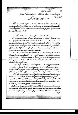
The schedule referred to in these Letters Patent and making part of the same, containing a description in the words of the said Carl Turnbull himself of his improvement in the Paddle Gate.
To all to whom these presents shall come.
Be it known that I, Carl Turnbull of Little Falls in the county of Westchester State of New York, have invented a new and useful improvement in the Paddle Gate for filling & emptying canal locks, letting water in & out of canals, & as a gate to be applied to all purposes for permitting or regulating the passage of water under a pressure or head.
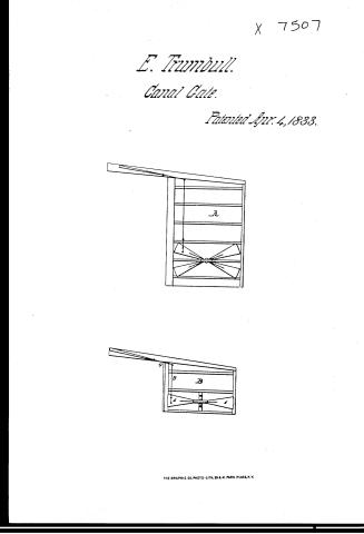
Said improvement is called the Radiating Paddle Gate, it may be made of cast or wrought iron or any other metal or of wood. The annexed drawing marked B. represents a large gate of a lock with the radiating paddle attached in its most simple form.
Fig. 1. represents two wings of the radiating paddle gate, covering orifices in the main gate, through which water is intended to pass. Said radiating paddle gate, is to be attached to the upper side of the canal gate thus on a center. The face of the radiating Paddle gate next to the large gate is a plane & slides on the planking of the large gate. On the outside of the radiating Paddle gate, as of the center, the gate is made thicker than at the ends of the wings in order to give it sufficient strength.
Where a large quantity of water is required to escape in a short time it may be advisable to add, an additional number of wings, as in figure 2, in the annexed drawing.
Page 3.
268. 7507X
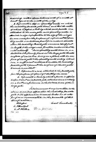
drawing, with a space between each of a width at least equal to the width of the wing.
2. Represents a step or operating center on which the radiating paddle gate turns, and that the center of which is passed a bolt by which said paddle is attached to the main gate, said operating center, is varied in size in proportion to the size of the wings, (in one used for the purpose of experiment the operating center was between four & five inches in diameter when the radiating Paddle gate was seven & half feet in length & the wings were fourteen inches wide at the outer extremity. Said operating center turns in a metallic box firmly fixed in the large gate, the outer surface of said box, being on a plane with the surface of said gate & the operating center sinking into said box, a sufficient distance to sustain the radiating paddle gate, & permit the surface of the two gates to come in contact.
3. Represents a rod, attached to the paddle gate, for the purpose of opening & shutting the same.
4. Represents a lever by which a power is applied to open & shut said paddle gate, attached to rod 3, & turning on a bolt as a fulcrum in the balance beam of the large gate.
I claim as new & my invention in the above described apparatus the radiating paddle gate & its application to canal locks and all purposes enumerated in the preamble of this specification.
Witnesses
Carl Zumbull
C. O. Hulbut
C. A. Miller
560 170.
Published accounts: journal notice
Notice in the monthly list of patents, with remarks
Journal of the Franklin Institute, new ser., vol. 12 (1833), p. 232 · View the page
1. For an improvement in the Paddle Gate, for canal locks; Earl Trumbull, Little Falls, Herkimer county, New York, April 4.
Remarks. The contrivance here patented is denominated a radiating paddle gate. It is in form like the valves sometimes used in the ash pits of stoves to regulate the draft. There may be two or more arms turning on a centre, and covering corresponding orifices cut in the lock gate. In order to open or close the paddle, a rod attached to the extremity of one of the arms, extends up to the top of the gate, where it is acted on by a lever. The gate is intended to be of cast iron, and is to increase in thickness as it narrows in approaching the centre. In one used for experiment, the circle of the centre was between four and five inches in diameter; the paddle gate seven and a half feet in length, and the ends of the wings fourteen inches wide.
About this record
- Patentee
- DATAMP
- Date
- the Name and Date index of patents, DATAMP, USPTO records
- Invention
- DATAMP
- Listed in
- the Name and Date index of patents, DATAMP, USPTO records, Jim Shaw's X-patent list, the Journal of the Franklin Institute, Burke's List of Patents (1847)
- Burke's 1847 Patent Office list gives the same patent.