

Drawings and documents
National Archives restored drawings: drawing
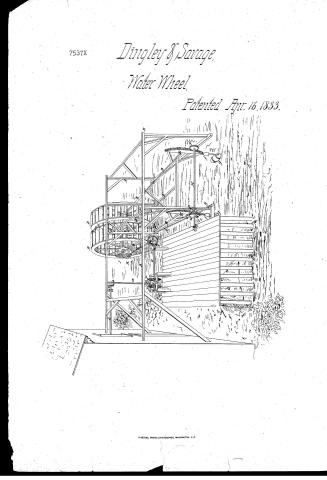
Amasa Dingley and Israel S. Savage's Patent Drawing for and Improvement in Tide and Current Water Wheels

National Archives, Restored Patent Drawings (Record Group 241) · Full-size scan at the National Archives · Catalog record
Show the text on the drawing Hide (210 words)
Words on the drawing as machine-read by the National Archives; not checked. Useful mainly for searching.
UYDRALL in MOTORS / Rotary. / Vol 17 page 293 / AMASA DINGLEY & ISREL S, SAVAGE / Impro in Tide and Current Water Wheels / CANADA / Patented April 16# 1833. / 7537.+ LIVISION / References / Frame for supporting the water wheels. / B,B,B, scale beam Levers / c,c,c, contropins / D,D, . . water wherls. / E,E, segment cog-wheels / F,F, pinion wheels, for regulating ther dipofter / water-wheets, / G,G, ratchet wheels, Porsecuring the water wherls / in any position / H, axla of the pinion wherls (F,F,) / J, cog wheel, on shaft of water wherls. / If, Crank- / J. / K, pinion, on shaft(I) supported on gudgeon(a,a) / NL, bevel cog where mashing into small / pinion (N) on shaft(0) / P.P, two bovel cog wheres on shaft(0) / Q, perpendicular shaft, having a pinion / (R,) on lower end, is made to workinto / either of the bruel cog wheels (P,P,) by / a shifting lever (s,) supported & turning / on pin(b), and by which the motion / of the wheel is reversed. / d, horizontal shaft with pinions (e) / for conveying the power to any distance / op / fg. weights. / g.g, Buoys / Patent Office June 371848 / Made under the direction of the / Commision / Palentz in conformity / with act 3. 1837 / Commifroner
USPTO scan
The patent as scanned by the USPTO
-
 Page 1
-
 Page 2
-
 Page 3


U.S. Patent and Trademark Office · Google Patents
Show the transcription Hide (874 words)
Machine transcription (LightOnOCR) of the pages as scanned by the USPTO, most of them the handwritten copies made when the records were restored after the 1836 fire. Not checked; it can misread handwriting, so compare it with the scan.
Page 1.
7537X
Dingley & Savage,
Water Wheel,
Patented Apr. 16, 1833.
Page 2.
7537X Oct. 16, 1833 299
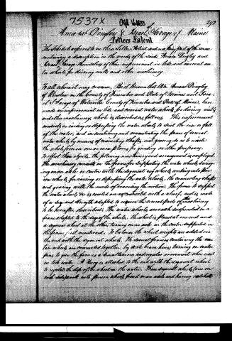
Amasa Dingley & Israel Savage of Maine
Letters Patent
The schedule referred to in these Letters Patent and making part of the same containing a description in the words of the said Amasa Dingley and Israel Savage themselves of their improvement in tide and current water wheels for driving mills and other machinery.
To all whom it may concern, Be it known that We Amasa Dingley of Winslow in the county of Kennebec and State of Maine and Israel Savage of Waterville County of Kennebec and State of Maine, have made an improvement in tide and current water wheels, for driving mills and other machinery, which is described as follows. This improvement consists in raising or depressing the water wheels to suit the rise or fall of the water, and in combining and concentrating the power of several water wheels by means of connecting shafts, and gearing so as to unite the whole force in one or more places for grinding or other purposes. To effect these objects, the following machinery and arrangement is employed. The machinery consists in the frame for supporting the water wheels swinging on an axle or centre with the segment cog wheels working into pinion wheels, for raising or depressing the water wheels, the connecting shafts and gearing with the mode of receiving the motion. The frame to support the water wheels is erected on an octagonal with a shaft, and is made of a size and strength adapted to receive the several parts of machinery to be hereafter described. The water wheels are each suspended on a frame adapted to the size of the wheels. This wheel is placed at one end and a segment wheel at the other, turning on an axle in the centre supported in the frame first mentioned. To balance the wheel weights are added on the end with the segment wheels. The several frames containing the water wheels are connected together by a scale beam hives turning on centre pins to give the frames a simultaneous and regular movement when used in tide water. A Hinge is attached to the end with the segment wheel to regulate the depth of the wheel in the water. These segment wheels (one on each side) work into pinion wheels fixed on an axle and having ratchet
Page 3.
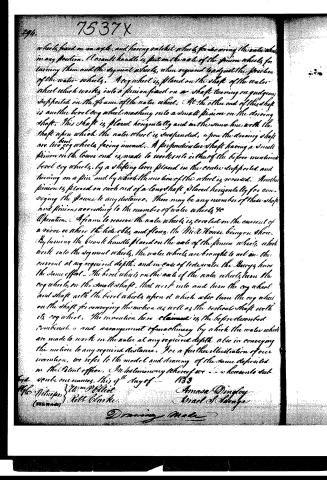
which, fixed on an axle, and having satellite wheels for bearing the water wheels in any position. A crank handle is put on the axle of the pinion wheels for turning them and the segment wheels, when required to adjust the position of the water wheels. A cog wheel is placed on the shaft of the water wheel which works into a pinion fixed on a shaft turning on guides supported on the frame of the water wheel. At the other end of this shaft is another bevel cog wheel meshing into a small pinion on the driving shaft. This shaft is placed horizontally and in the same line with the shaft upon which the water wheel is suspended; upon the driving shaft are two cog wheels facing inward. A perpendicular shaft having a small pinion on the lower end is made to work into either of the before mentioned bevel cog wheels, by a shifting lever placed in the centre supported and turning on a pin and by which the motion of the wheel is reversed. Another pinion is placed on each end of a long shaft placed horizontally for conveying the power to any distance. There may be any number of these shafts and pinions according to the number of water wheels, &c.
Operation. A frame to receive the water wheels is erected on the current of a river or where the tide ebbs and flows, the Mill House being on shore. By turning the crank handle placed on the axle of the pinion wheels, which work into the segment wheels, the water wheels are brought to act on the current at any required depth, and in case of tide water the Bevels have the same effect. The bevel wheel on the axle of the water wheels turn the cog wheels on the small shaft, that work into and turn the cog wheel and shaft with the bevel wheels upon it which also turn the cog wheel on the shaft for conveying the motion as well as the vertical shaft with its cog wheel. The invention here claimed is the before described combination and arrangement of machinery by which the water wheels are made to work in the water at any required depth, also in conveying the motion to any required distance. For a further illustration of our invention, we refer to the model and drawing of the same deposited in the Patent office.
In testimony whereof we - - - hereunto set our hands, this 4th day of - 1833
Wm. B. Elliot
H. H. Harper
H. H. Clarke
Amasa Dingley
Israel S. Savage
Drawing Made
Published accounts: journal notice
Notice in the monthly list of patents, with remarks
Journal of the Franklin Institute, new ser., vol. 12 (1833), p. 244 · View the page
32. For Tide and Current Water Wheels; Amasa Dingley, of Winslow, and Israel S. Savage, of Waterville, Kennebeck county, Maine, April 16.
Remarks. The proper frame work for supporting the water wheels, and other parts of the machinery, is to be erected upon a wharf or other suitable place, the mill house being on the shore, and the power obtained being communicated by shafts properly geared. There may be two or more water wheels, each having its proper gearing, so as to obtain their united effect. The water wheels are to be placed upon shafts which may be raised and lowered by means of a pinion and segment wheel, thus regulating their dipinto the water. "The invention claimed is the combination and arrangement of machinery, as described, by which the water wheels are made to work in the water at any required depth; also in conveying the motion to any required distance." It was necessary for the patentees to limit themselves to the arrangement which they have described and represented, as tide and current wheels are in themselves no novelties, having been very frequently erected. The mode of construction shown in the drawings does not appear to hold out any promise of greater success than has heretofore resulted from similar plans, as it is not more simple, or in any way likely to be more efficient. In most instances tide and current wheels have been failures, as there are but few situations where more convenient and safe modes of obtaining power do not present themselves.
About this record
- Patentee
- DATAMP
- Date
- the Name and Date index of patents, DATAMP, USPTO records
- Invention
- DATAMP
- Listed in
- the Name and Date index of patents, DATAMP, USPTO records, Jim Shaw's X-patent list, the Journal of the Franklin Institute, Burke's List of Patents (1847)
- Burke's 1847 Patent Office list gives the same patent.