

Drawings and documents
National Archives restored drawings: drawing
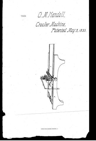
George M. Kendall's Patent Drawing for a Cracker Machine

National Archives, Restored Patent Drawings (Record Group 241) · Full-size scan at the National Archives · Catalog record
Show the text on the drawing Hide (52 words)
Words on the drawing as machine-read by the National Archives; not checked. Useful mainly for searching.
65) KITCHEN UTENSILS. a / 65. KITCHEN UTENSILS. (6) Bread and Cracker Machines. / [6] Cracker Mach's / Groge Mi KENDALL'S / Stampers / $150 / CRACKER MACHINE. / CLASSIFICATION / 7565-X / - Patented May 3ed 3 1833.- / DIVISION. / sare springs under holler / dio / under the bourd C,
USPTO scan
The patent as scanned by the USPTO
-
 Page 1
-
 Page 2
-
 Page 3
-
 Page 4


U.S. Patent and Trademark Office · Google Patents
Show the transcription Hide (981 words)
Machine transcription (LightOnOCR) of the pages as scanned by the USPTO, most of them the handwritten copies made when the records were restored after the 1836 fire. Not checked; it can misread handwriting, so compare it with the scan.
Page 1.
7565X
G. M. Kendall,
Cracker Machine,
Patented May 3, 1833.
Page 2.
May 3, 1833
George M. Hudson, Yonkers N.Y.
Sitters: Patent
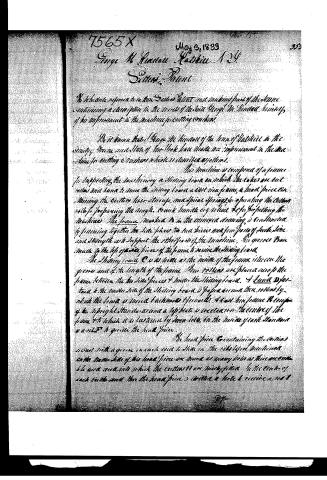
The Inventor refers to his two Series Patent and making part of the same containing a description in the name of the said George M. Hudson, himself, of his improvement in the machine for cutting vouchers.
It is known that George M. Hudson of the town of Yonkers in the county of Westchester and State of New York have made an improvement in the machine for cutting vouchers which is described as follows.
The machine is composed of a frame for supporting the machinery & sliding board on which the cakes are cut, rollers and bands to move the sliding board, a cast iron frame, a head piece containing the cutter, lever, straps, and spiral springs for operating the cutter, rolls for preparing the dough, crank handle or wheel & for propelling the machine. The frame marked A in the annexed drawing is constructed by joining together two side pieces, two end pieces and four pieces of back side and strength to support the other parts of the machine. The pieces B are made in the top of the side pieces of the frame to receive the sliding board.
The sliding board C is as near as the inside of the frame, between the pieces and of the length of the frame. The rollers are placed across the frame between the two side pieces & under the sliding board. A band D fastened to the under side of the sliding board & paper around these rollers by which the board is moved backwards & forwards. A cast iron frame E composed of the upright standards and a top plate is erected on the center of the frame & to which it is fastened by iron bolts. On the inside of each standard is a slot to guide the head piece.
The head piece G containing the cutters is cast with a groove on each side to slide on the rollers before mentioned. On the under side of this head piece are found as many holes as there are cutters & the area over which the cutters H are nicely placed. In the center of each cutter and also the head piece is drilled a hole to receive a rod.
Page 3.
to the two ends of which rods are attached the following working in the cutter the upper one is fastened to the top plate of the frame. The locking wires are inserted into the cutters in the usual manner. A movable frame composed of two parts - a cap is fastened on the top of the head piece.
The parts or side pieces of the frame are round bars of iron passing loosely thru openings in the top plate of the cast iron frame. In the center of the cap piece of the movable frame is a small standard R. The two L's is made of iron of suitable length & strength to span the cutters and extend across the frame having one end attached to iron spring fast N by a pin which it turns and is connected with the movable frame by an other pin, L, passing thru the top of the small standard & lever. The other end of the two cutters are the side of the machine having a stringy flap O attached to it by which it is operated. Spiral springs P are put around the parts of the movable frame, one end of each spring resting on the plate of the cast iron frame & the other end bearing against the under side of the cap piece of the movable frame.
The roller Q for rolling the dough to a proper thickness is placed atop the top of the frame near the cutters its quaggers turning in the table L by B graduated by screws and spiral springs S to any thickness of cakes required. One of the quaggers projects sufficiently far to receive a cog wheel T and a crank handle V. This cog wheel works into another cog wheel V in the end of the quaggers of two of the rollers carrying the hand and sliding board. The operation of the machine is as follows.
The dough is prepared in the bake; it is then laid upon the sliding board, the crank handle turned which brings forward the sliding board with the dough unto the roller where it is rolled to a proper thickness it is then carried forward unto the cutters the operator first puts into the string at the end of the two and pushes down which brings down the end of the lever and with it the movable frame & cutters. The cakes are turned and stacked; the first is then raised and the movable frame returns to its former position by the action of the spiral springs, at the same time the cakes are discharged from the cutters by the followers on the ends of the rods.
Page 4.
In this manner the operation is continued. The roller and upper clamps are moved in the ordinary mode. I propose, however, the rollers working into a rack on the under side of the movable beam, may be substituted for the rollers and levers to move the beam.
What I claim as my invention in the type movable machine is the application of the spiral spring lever and strip, applied to the movable beam as described in cutting machines.
In testimony whereof I have set my hand to this 29 day of April 1836.
George W. Hudson
Witness
William Elliot
William Shand
(On a post folio)
Published accounts: journal notice
Notice in the monthly list of patents, with remarks
Journal of the Franklin Institute, new ser., vol. 12 (1833), p. 310 · View the page
3. For a Machine for cutting Crackers; George M. Kendall, Katskill, Greene county, New York, May 3.
Remarks. The dough from which the crackers are to be made is placed upon a sliding table, that is moved forward by turning a crank, which crank also carries a roller above the board, so set as to reduce or roll the dough to its proper thickness. As the dough escapes from the roller, it passes immediately under a row of cutters extending across the board, and sliding up and down in a suitable frame. The cutters are connected together, are brought down by a lever, and are raised again by spiral springs which surround their shafts. Dockers are placed within the cutters, and also pistons which force the crackers out as the cutters are raised. The lever is made to descend by placing the foot in a stirrup suspended from it. The claim is to " the application of the spiral springs, the lever, and stirrup operated upon in the manner above described."
About this record
- Patentee
- DATAMP
- Date
- the Name and Date index of patents, DATAMP, USPTO records
- Invention
- DATAMP
- Listed in
- the Name and Date index of patents, DATAMP, USPTO records, Jim Shaw's X-patent list, the Journal of the Franklin Institute, Burke's List of Patents (1847)
- The Franklin Institute's journal spells the name differently.
- Burke's 1847 Patent Office list gives the same patent.