

Drawings and documents
National Archives restored drawings: drawing
Stephen H. Long's Patent Drawing for a Steam Boiler

National Archives, Restored Patent Drawings (Record Group 241) · Full-size scan at the National Archives · Catalog record
Show the text on the drawing Hide (69 words)
Words on the drawing as machine-read by the National Archives; not checked. Useful mainly for searching.
122. STEAM. / Borters S Eugenes / 2. BOILERS. / [148] Fire Tubo. / STEPHEN H LONG'S. / wheels #2- / STEAM BOILER 0 Ic. / PATENTED. / 6Th may 18330 / CLASSIFICATION / v.16./2.303. / 7570-+ / DIVISION. / Fig /. / Fr / Fig.5. / Q= / JuG / /- / 7. / /- / GL] / PG / b. / to / V. / In / G- / F a / IL / Fre 2. / of Fig. 4. / Q=[ / 100 / he / It / 1 1 I ] ] I'} I I I L/ I . / 11,
USPTO scan
The patent as scanned by the USPTO
-
 Page 1
-
 Page 2
-
 Page 3
-
 Page 4
-
 Page 5
-
 Page 6
-
 Page 7
-
 Page 8
-
 Page 9
-
 Page 10
-
 Page 11


U.S. Patent and Trademark Office · Google Patents
Show the transcription Hide (3,542 words)
Machine transcription (LightOnOCR) of the pages as scanned by the USPTO, most of them the handwritten copies made when the records were restored after the 1836 fire. Not checked; it can misread handwriting, so compare it with the scan.
Page 1.
7570X
S. H. Long,
Steam-Boiler Fire-Tube.
Patented May 6, 1833.

AM. PHOTO-LITHO. CO. N. Y. (OSBORNE'S PROCESS)
Page 2.
May 6, 1833
Stephen H. Long U.S. Army
Letters Patent
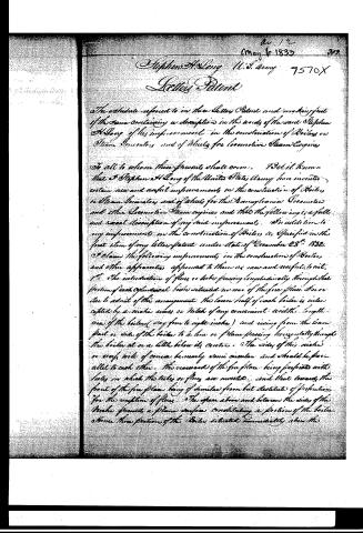
The certificate referred to in the Letters Patent and making part of the same containing a description in the words of the said Stephen H. Long of his improvement in the construction of Boilers or Steam Generators and of Wheels for locomotive Steam Engines.
To all to whom these presents shall come. I, Stephen H. Long of the United States Army, have invented certain new and useful improvements in the construction of Boilers or Steam Generators and of wheels for the Army, Locomotive and other Locomotive Steam engines, and that the following is a full and exact description of my said improvements. In addition to my improvements in the construction of Boilers as specified in the first item of my Letters Patent under date of December 28th, 1832. I claim the following improvements in the construction of Boilers and other apparatus appended to them as new and useful to wit:
1st. The introduction of flues or tubes passing longitudinally through that portion of each cylindrical boiler situated in rear of the fire place, so as to admit of the arrangement the lower half of each boiler is divided by a series across or Niches of any convenient width lengthwise of the boiler (say four to eight inches) and rising from the lower part or side of the boiler to a line or plane passing horizontally through the boiler at or a little below its centre. The sides of this niche or recess will of course be nearly semi-circular and should be parallel to each other. The rearward of the fire place being perforated with holes in which the tubes or flues are inserted, and that toward the front of the fire place being of similar form but destitute of perforations for the reception of flues. The space above and between the sides of the niche presents a plane surface constituting a portion of the boiler. Hence that portion of the Boiler situated immediately above the
Page 3.
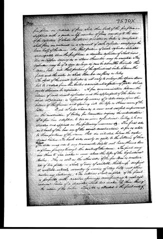
fire place are suitable of flues, while the back of the fireplace are supplied with a greater number of flues according to the size of the cylinders, of which the steam generator or boiler is composed, which flues are contained in a segment of each cylinder, occupying the lower half of the same. On that portion of each cylinder situated immediately above the fireplace, a smaller cylinder of sheet iron or copper serving as a steam chamber may be inserted. This cylinder may be of a size as large as can be admitted through the man-hole into that portion of the cylindrical boiler between the front and the back in which there are no flues or tubes. The object of the small cylinder is not only to enlarge the steam room but to exclude from the boiler a considerable portion of water which would otherwise be required. A free communication between the interior of each small cylinder and the upper part of the boiler in which it is situated is afforded by means of a tube rising from the bottom of the former and opening into the top or steam room of the latter.
2nd. I also claim as a new and useful improvement in the construction of boilers for locomotive engines, the introduction of a fire box adapted to two or more cylindrical boilers to be connected and applied in the following manner: The front side and back of the box are of the usual construction so far as relates to those portions of the same that are situated below the cylindrical boilers. The back side nearly or quite to the bottom of the boilers. The sides may rise to any convenient height not lower than a line or plane passing through the center of the same. The front may rise there to six inches or more above the tops of the cylindrical boilers. This as well as the other sides of the fire box is constructed of two plates or sheets of iron of suitable thickness, confined at suitable intervals, together by means of stay bolts and other customary fastenings. The interior sheet or plate of the front is perforated with circular openings corresponding to each cylindrical boiler of a diameter about two inches less than that of the interior of the boiler. This plate is attached to the front ends of
Page 4.
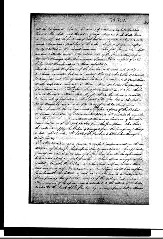
all the cylindrical boilers by means of rods or stay bolts passing through the plate and through a flange about one inch wide turned inwardly at the front end of each boiler and made continuous past round the interior periphery of the boiler. These confined and afterwards welded in the usual manner. The plate forms a steamtight junction with the boilers. The extreme state of the front is also perforated with openings after the manner of man holes in front of each boiler and corresponding to them respectively.
This arranged the front of the fire box will serve not only as a steam generator but as a conduit through which the water to be conveyed into the cylindrical boilers in a manner to keep them equally supplied and will at the same time act as the primary of a steam pump leading from the cylindrical boilers but from the fire box to the main steam pipe through which the steam is conducted to the working cylinders. The front of the fire box is also perforated in usual by one or more fire doors of suitable dimensions.
In reference to the arrangement of different parts of the boiler as a steam generator as above contemplated it should be remarked that the chimney is situated at the rear or back end of the cylindrical boilers or at the end farthest from the fire place. Also that the water to supply the boilers is conveyed from the fire place through a tube which enters the back of the fire box a little below the cylindrical boilers.
3d. I also claim as a new and useful improvement in the construction of boilers, for the purposes already mentioned, the application of an apron articulated in rear of the fire box beneath the cylindrical boilers and about one inch from them which apron may pass horizontally beneath the boilers and the space or spaces between them and may run either in a curve or in an oblique right line or plane from beneath the bottom of each exterior boiler to a horizontal plane passing through the centers of the cylindrical boilers. The margins of the apron may be attached to the outside of the boilers as also to the back of the fire box by means of screws bolts or rivets.
Page 5.
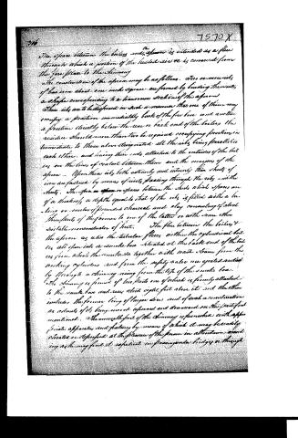
The space between the boilers and the apron is intended as a flue through which a portion of the heated air is conveyed from the fire place to the chimney.
The construction of the apron may be as follows. Two or more ribs of bar iron about one inch square are formed by bending them into a shape corresponding to a transverse section of the apron. These ribs are to be disposed in such a manner that one of them may occupy a position immediately back of the fire box and another a position directly below the rear or back end of the boilers. The residue should more than two be required occupying positions intermediate to those above designated, all the ribs being parallel to each other, and having their ends attached to the outsides of the boilers on the lines of contact between them and the margins of the apron. Upon these ribs, both exteriorly and interiorly, thin sheets of iron are fastened by means of rivets passing through the ribs and the sheets. The space or spaces between the sheets which spaces are of a thickness or depth equal to that of the ribs is filled with a burning or smoldering pounded charcoal and clay consisting of about three parts of the former to one of the latter or with some other suitable nonconductor of heat.
The flue between the boilers and the apron, as also the tubular flues within the cylindrical boilers, all flow into a smoke box situated at the back end of the boilers from which the smoke is together with waste steam from the working cylinders and from the safety valve are ejected vertically through a chimney rising from the top of the smoke box. The chimney is formed of two parts one of which is firmly attached to the smoke box and rises about eight feet above it and the other includes the former being of larger diameter and of such a construction as admits of its being moved upward and downward on the part just mentioned. The movable part of the chimney is furnished with appropriate apparatus and fixtures by means of which it may be readily elevated or depressed at the pleasure of the person in attendance according as he may find it expedient in passing under bridges or through
Page 6.
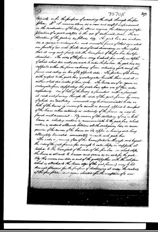
tunnels, or for the purpose of increasing the draft through the fire place. N. B. I. moreover claim as a new and useful improvement in the construction of boilers for steam engines, the discovery and application of a grate adapted to the use of anthracite coal. The construction of the grate is as follows viz. The grate bars are included in a square or rectangular and movable frame of sheet iron about one fourth of an inch thick and of such dimensions in other respects that it may enter freely into the lower part of the fire box hereinafter described. The sides of the frame may be about five inches in depth of which about two inches are made to enter the fire box. The grate bars are supported within the frame on beams of iron extending quite across the frame and resting in two of its opposite sides. The position of the beams with respect to the grate bars is rectangular beneath them and at or within about six inches of their ends. The beams are of a square or rectangular form supporting the grate bars upon one of their sides respectively. One of both of the beams is furnished with a journal at each end passing through the side of the grate frame by means of which an oscillatory movement may be communicated to one or both of the beams by means of a wheel or wrench applied to some part of the beam either externally or internally of the frame as may be found most convenient. By means of the oscillation of one or both beams a vibratory motion is communicated to the grate bars which motion is rendered alternate between all the contiguous bars in consequence of the convexity of the beam on its upper or bearing side being alternately increased immediately beneath each grate bar. The ends of journals of one of the beams projects through and beyond the sides of the grate frame far enough to enter steps or supports attached to the lower part of the sides of the fire box in which steps the beam is allowed to traverse and serves as an axle for the grate. By this means one side or end of the grate (together with the ash pan which is attached to the lower edge of the grate frame) may be let down or drawn for the purpose of discharging at once the contents of the fire place and again elevated for the reception of a new
Page 7.
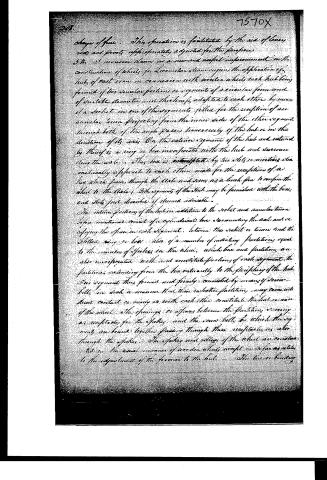
chaps of flue. This operation is facilitated by the aid of lever rods and pivots appropriately adjusted for the purpose.
The 2d invention claims as a new and useful improvement in the construction of wheels for locomotive steam engines the application of hubs of cast iron in connection with wooden wheels each hub being formed of two similar portions or segments of a circular form and of suitable diameter and thickness, adapted to each other by means of a socket in one of the segments, filled for the reception of an annular tenon projecting from the inner side of the other segment through both of the angle pieces transversely of the hub or in the direction of its axis. On the exterior segment of the hub and outward by thereof is a ring or box incorporated with the hub and surrounding the axle. This box is interrupted by two slots or notches diametrically opposite to each other made for the reception of a key which passes through the axle and serves as a latch pin to confine the wheel to the axle. Each segment of the hub may be furnished with the box and slots just described if deemed advisable.
The interior portions of the hub in addition to the socket and annular tenon before mentioned consist of an additional box surrounding the axle and occupying the space in each segment between the socket or tenon and the slotted ring or box, also of a number of radiating partitions equal to the number of spokes in the wheel, which box and partitions are also incorporated with and constitute portions of each segment. The partitions extending from the box radially to the periphery of the hub. The segments thus formed and firmly connected by means of screw-bolts in such a manner that their radiating partitions may come into direct contact as nearly as with each other constitute the hub or inner of the wheel. The openings or spaces between the partitions or rings are receptacles for the spokes and the same bolts by which the segments are bound together passing through these receptacles, are also through the spokes. The spokes and gullets of the wheel are constructed in the usual manner of wooden wheels except in so far as relate to the adjustment of the former to the hub. The box or binding
Page 8.
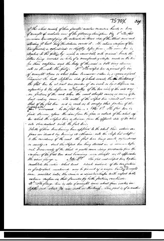
of the wheel consists of three parallel circular concentric bands or lines of wrought or malleable iron of the following description. Fig 1st The flat iron which has occupying the outermost or stem side of the wheel iron and extending at least half the distance across it. The exterior surface of this line presents a cylindrical or slightly taper form. The inner line is attached to the felling by nails or screw bolts with conical heads the latter being inserted in holes of a corresponding shape made in the line for their reception and the body of the nail or bolt being driven into or through the felling. 2nd The sloped line is formed of a bar of wrought iron or steel whose transverse section is a square or plant like form the least depth or side of which equals the thickness of the flat line by at least one quarter of an inch or by a difference corresponding to the difference in lengths of the two sides of the rail way in portions of the road when the most abrupt curves or curves of the least radius occur. The width of the sloped line should not exceed that of the flat line and is such as to occupy that portion of the length of the iron uncovered by the flat line. 3rd The flat line is first driven upon the iron from the face or outside of the wheel upon which the sloped line is driven from the opposite side of the wheel into close contact with the flat line.
When of these lines having been applied to the wheel their exterior surfaces are dressed by turning or abrasion into the shape best adapted to the curvature of the road the flat line being made cylindrical or nearly so and the sloped line being dressed in a manner to present transversely of the wheel a gentle curve rising gradually from the surface of the flat line and becoming more abrupt as it approaches the wheel flange. 4th The flat and sloped lines together constitute the entire wheel tread which instead of the two portions or parts just mentioned may be formed of a single band of wrought iron moulded into the same or similar shape with respect to its exterior surfaces as that presented by both portions combined. 5th The flange line is also of wrought iron about four inches in depth and about 3/4 inch in thickness this part is of a width
Page 9.
7570X
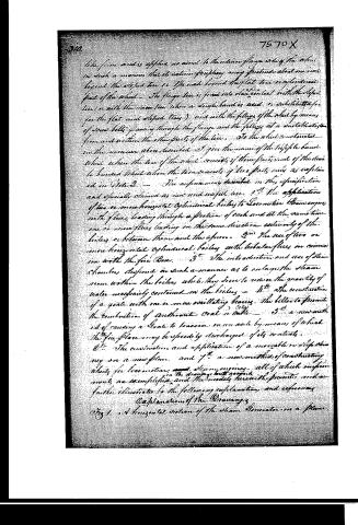
The front end is applied in usual to the inner flange side of the wheel in such a manner that its exterior flange may protrude about one inch beyond the deflector tire or the ends beyond the flat tire in adjacent part of the wheel. The flange tire is fixed into close contact with the deflector tire or with the inner tire when a single band is used, or substituted for the flat and deflector tires, and with the felling of the wheel by means of screw bolts passing through the flange and the felling at a suitable distance from and within the other parts of the tire. To the wheel constructed in the manner above described I give the name of the triple flange band wheel when the tire of the wheel consists of three parts, and of the double band wheel when the tire consists of two parts only as explained in Note 2.
The improvements described in this specification and especially claimed as new and useful are:
1st. The application of two or more horizontal cylindrical boilers to locomotive steam engines with flues leading through a portion of each and at the same time one or more flues leading in the same direction exteriorly of the boilers or between them and the apron.
2nd. The use of two or more horizontal cylindrical boilers with tubular flues in connection with the fire Box.
3rd. The introduction and use of steam chambers disposed in such a manner as to enlarge the steam room within the boilers while they serve to reduce the quantity of water necessarily contained in the boilers.
4th. The construction of a grate with one or more oscillating beams, the bells to promote the combustion of anthracite coal or coke.
5th. A new method of causing a grate to traverse in an arc by means of which the fire place may be speedily discharged of its contents.
6th. The construction and application of a movable or self-cleaning fire or a new fire.
7th. A new method of constructing wheels for locomotive and steam engines, all of which improvements are exemplified in the drawings herewith presented and are further illustrated by the following explanation and references.
Explanation of the Drawings
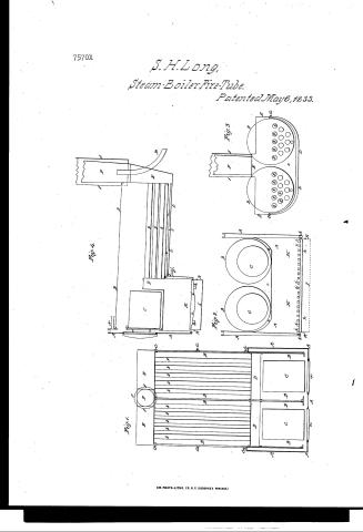
Fig 1. A horizontal section of the steam generator on a plane
Page 10.
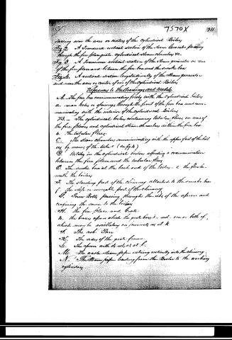
passing near the axes or centers of the cylindrical Boilers.
Fig 2. A transverse vertical section of the Steam Generator passing through the fire place grate, cylindrical Steam chamber, &c.
Fig 3. A transverse vertical section of the Steam generator in use of the fire place and between the fire box and the smoke box.
Fig 4. A vertical section longitudinally of the Steam generator and near the axis or center of one of the cylindrical Boilers.
References to the Drawings and Models.
A. The fire box communicating freely with the cylindrical boilers.
B. Man holes or openings through the front of the fire box and communicating with the interior of the cylindrical boilers.
C. The cylindrical boilers containing tubular flues, in rear of the fire places and cylindrical Steam chambers within the fire box.
D. The tubular flues.
E. The steam chambers communicating with the upper part of the boilers by means of the tubes C (in fig 4).
F. Holes in the cylindrical boilers affording a communication between the fire place and the tubular flues.
G. The smoke box at the back end of the boilers - C the flue beneath the boilers.
H. The standing part of the chimney attached to the smoke box.
I. The slip or movable part of the chimney.
J. Screw bolts passing through the ribs of the apron and confining the same to the boilers.
K. The fire place and Grate.
L. The braces upon which the grate bars are set, one on both of which may be oscillating on journals as at K.
M. The ash Pan.
N. The sides of the grate frame.
O. The apron with its ribs as at L.
P. The waste steam pipe entering vertically into the chimney.
Q. The Steam pipes leading from the Boilers to the working cylinders.
Page 11.
7570X
Q. The supply pipe for conveying water into the boiler
P. The wheel with its appropriate fixtures.
The testimony that the above is a true specification of my said improvements as above described. I have hereunto set my hand and seal this 21st day of February A.D. 1833.
Witnesses
Jacob P. Wolfe
J. Badger
Stephen A. Long.
3804 n 85
(Or in post folio)
Published accounts: journal notice
Notice in the monthly list of patents, with remarks
Journal of the Franklin Institute, new ser., vol. 12 (1833), p. 312 · View the page
8. For Boilers, or steam generators, and Wheels, for Locomotive Engines; Stephen H. Long, Colonel of the United States Engineer Corps, May 6.
Remarks. The improvements claimed in this patent are stated to be in addition to those described by the patentee in the specification of his patent of December 28th, 1832, which was noticed in the last volume; to this, therefore, we refer. "The improvements described in this specification and specifically claimed as new and useful, are, 1st, the application of two or more horizontal, cylindrical boilers to locomotive steam engines, with flues leading through a portion of each, and, at the same time, one or more flues leading in the same direction exteriorly to the boilers, or between them and the apron. 2nd. the use of two or more horizontal cylindrical boilers with tubular flues, in connexion with a fire box. 3d. the introduction and use of steam chambers, disposed in such a manner as to enlarge the steam room within the boilers, while they reduce the quantity of water necessarily contained in the boilers. 4th. the construction of a grate with one or more oscillating bearers, the better to promote the combustion of anthracite coal or coke. 5th. a new method of causing a grate to traverse on an axle, by means of which the fireplace may speedily be discharged of its contents. 6th. the construction and application of a movable, or slip, chimney, on a new plan; and 7th. a new method of constructing wheels for locomotive steam engines." We shall offer a slight sketch of some of these improvements, whilst others will necessarily be neglected, as they could not be well described without very extensive drawings. The flues, or tubes, alluded to in the first item, are to pass longitudinally through that portion of each cylindrical boiler which is situated in rear of the fireplace. The movable, or slip, chimney, consists of one chimney sliding within another, like the tubes of a telescope, with suitable contrivances for raising or lowering the sliding part in passing under bridges, &c. What is the particular construction of the grate, with the oscillating bearers, we do not fully perceive, even with the aid of the drawings, which do not furnish any details, the model, which we have not seen, has probably been relied on to render this point clear, a proceeding, by the way, which we have repeatedly reprehended. By means of levers, which are attached to a pivot, or axle, one side, or end, of the grate may be let down, for the purpose of discharging the contents of the fireplace. The wheels are to have cast iron hubs, with wooden felloes and spokes. The hubs are to be cast in two pieces, divided vertically through the boxes, or mortises, for the spokes, and having on one half a projecting ring, to fall into a corresponding hollow in the other. The two segments are to be secured together by suitable bolts, and are to be fastened to the axle by bolts passing through notches and mortises, in the manner of a linchpin. The spokes and felloes are to be made in the usual manner. The tire is to be made in two widths; one, which is the outer part of the rim, or tread, is to be flat, and of wrought iron; the inner portion is to be of wrought iron, or of steel, and is to be so formed as to rise conically towards the inner part of the tread, so as to adapt it to the different curvatures of the road. The flanch is to consist of a separate hoop of wrought iron, which is to be bolted on to the felloes on the inner side of the wheel. A wheel thus constructed the inventor denominates "the tripple banded wheel." It is proposed sometimes, however, to form the flat and conical parts of the tread of one piece, so that the wheel shall be double banded only, the flanch forming the second band. The wheel, thus described, is not represented in the drawings, which certainly ought to have been done, in conformity with the requirements of the law to "accompany the whole with drawings and written references, whenever the nature of the case admits of drawings.
About this record
- Patentee
- DATAMP
- Date
- the Name and Date index of patents, DATAMP, USPTO records
- Invention
- DATAMP
- Listed in
- the Name and Date index of patents, DATAMP, USPTO records, Jim Shaw's X-patent list, the Journal of the Franklin Institute, Burke's List of Patents (1847)
- Burke's 1847 Patent Office list gives the same patent.