

Drawings and documents
National Archives restored drawings: drawing
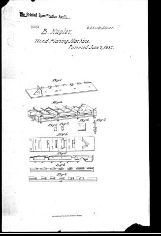
B. Kugler's Patent Drawing for a Planing Machine


National Archives, Restored Patent Drawings (Record Group 241) · Full-size scan at the National Archives · Catalog record
Show the text on the drawing Hide (398 words)
Words on the drawing as machine-read by the National Archives; not checked. Useful mainly for searching.
Sheet 1. 140 / 144 WOOD-WORKING MACHINES. / CLASSIFICATION / Planers, Sliding. / 7605. X / KUGLER'S. / References / DIVISION. / PLANING MACHINE. Sumber / "Is Longi Indinal Section of the Holding-Bor YI'mbers, / AA One of The Timbers, / Patented 3.June 7833, / Plate 1st / BBB The bloc Ks to Meepthe Ewo Timbers Se berate from / each other at their proper distances. / Lever lywhich boardes part ntothe box laterally / Fig' 6 / DD The endless plate Chain passing around the Cog Wheels F.F. / A The Dogg Kept n splace / G The cavety of the Holding 730X- / HH Doggs ting. and no in The affere nt groves / IIII The guages to regulate the boards entering cHolding box. / h a Space for the bla neto / In stay to mevent the planefrom moving / 00 / Fig2 A side viézs of he Dogg / 3 An End vierof he Dogg- / 44 bottom remot menDogg / 5 A partof the Žever to pizsh the Board the / machine / (Holding Box / 100% / Put together complete, / A asliding bedestal Zo tighten the Chainplate / BBBB part of the laversto Dush the boa T'd into the Boy holding / on a counter weight to bring the leversback / after they have pushed the board into the holding Box / D the plane. / TII me grages. / Eig 4 / Fig 3 / Fig 2 2 / 145 / y/o / Fig 1 / to
Sheet 2. Plate. 2nd. / Figl. / Fig. 1. / The Lottom plate with the bottom blocks / A The bottom plate / B The bottom blocks / Fig8. / c The stay to keep the side plates / in their proper position / Fir. 2. / A lateral men of the side plate / with the side blocks / A The side plate / B The side blocks / c The anterior side block / Fro.3. / A perpendicu lar view of the side plate / with the side blocks / A Theside plate / BB blocks. / Fig 6. / Fig 7. / anterior blocks. / Fig. 4. / A vien of the under surface of the top plates. / Figh. / Fig 6. / AAA / Diferent outting lits. / BB Holes for the re ns to moove,m / Fig. 5. / A the under surface / of the top plates. / Fio. 6.6.6. / A vien of the diferent planingb / Fig 4. / Figure y / A vzen of the serero bolts with the to / Gague scren passing thro / regulate the nid of the / side tate's / Fig.8. / The planing box complete. / The neek stit / screw lynhieh the plate / is fastened together. / The screw by nhich the bits / are regulated. / Fig 5. / Fig: 3. / Fig ch 2. / 144 WOOD-WORKING MACHINES. / Planers, Sliding. / CLASSIFICATION / 5. X 7605.X DIVISION / OIR
USPTO scan
The patent as scanned by the USPTO
-
 Page 1
-
 Page 2
-
 Page 3
-
 Page 4
-
 Page 5
-
 Page 6
-
 Page 7
-
 Page 8
-
 Page 9
-
 Page 10


U.S. Patent and Trademark Office · Google Patents
Show the transcription Hide (3,684 words)
Machine transcription (LightOnOCR) of the pages as scanned by the USPTO, most of them the handwritten copies made when the records were restored after the 1836 fire. Not checked; it can misread handwriting, so compare it with the scan.
Page 1.
No Printed Specification Available.
7605X
B. Kugler,
Wood Planing Machine.
Patented June 3, 1833.
2 Sheets-Sheet 1.
Fig. 1
Fig. 8.
Fig. 6 Fig. 6.
Fig. 4.
Fig. 5
Fig. 3.
Fig. 2.
AM. PHOTO-LITHO. CO. N.Y. (OSBORNE'S PROCESS)
Page 2.
No Printed Specification Available
7605X
B. Kugler,
Wood Planing Machine.
Patented June 3, 1833.
2 Sheets. Sheet 2.
Fig. 1.
Fig. 2.
Fig. 3.
Fig. 4.
Fig. 5.
Fig. 6.
AM. PHOTO-LITHO. CO. N. Y. (OSBORNE'S PROCESS)
Page 3.
17605 X
Benjamin Taylor. Phil. Penn
Sellers Patent
June 5 1839
339
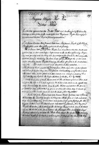
The undersigned refers to his Sellers Patent and makes part of the same containing a description to the same of the said Benjamin Taylor's invention of his Improvement Called Taylor's Planing Machine.
It is known to all men that Benjamin Taylor of the City of Philadelphia and State of Pennsylvania hath invented and applied to use a new and useful improvement in the Art of planing large long saw graining and cutting into sawings either plank boards or any other material used for reducing the same to an equal thickness viz a new and useful machine Called Taylor's Planing Machine specified in the words following.
His improvement and machine is thus described.
The pieces of timber called the Timbers from twelve to fourteen inches square and about forty feet long are to be placed horizontally and fastened to each other about nine inches apart and one end on a solid foundation (R.1. Fig 1. & 2) they are kept at the proper distance by blocks (R.1. Fig 1 & 2 & 3).
On the new face of each Timber and at the distance of about three inches from the top is to be cut a groove two inches wide and one inch deep running horizontally the whole length of the Timbers and called the groove (which is then deliverable) the groove as above described may be made as cut over or other fashion and let into the timber (R.1. Fig 1 & 2 & 3).
On the top of the Timbers and not nearer than one inch by seven feet is placed horizontally the Holding Box of a rectangular shape open at both ends and large enough to contain and admit of a passing way for the largest timber and thickest board intended to be planed (R.1. Fig 1 & 6).
Through the centre of the bottom of the Holding Box (which must be thin) by no the ends of the space between the Timbers there must be a longitudinal opening called the Stick Slot, about two inches wide running the whole length of the Box so as to leave a free passage for the sticks of the Box.
Page 4.
362. 1605
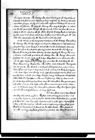
hereinbefore described. The holding Box must be as long as the longest beam is intended to be placed and capable of being adapted (by means of movable and slidable gauges, A 1 Fig 1 & C. 115) to the different widths of the beam is intended to be placed. The top of the Holding Box may be left open in which case the Box must be fed through the top, and the beam must come down actually in the box vice form its top. If the top of the Holding Box be not left open the side must be left so, in which case the Box must be fed through the side. With these modes of feeding the Box are hereinbefore described.
In the windows at the ends of and contiguous to the Holding Box is placed the Manning Box, A 1 Fig 6 D) of a rectangular shape open at both ends, about three feet long, wide enough to admit the beams as hereinbefore described, and having a horizontal opening (called the neck slit, A 2. Fig 5 A) through the centre of the bottom extending the whole length of the Manning Box and of the same width as the neck slit in the Holding Box. The Manning Box is to be so placed that the upper surface of the bottom thereof shall be in a horizontal line with the upper surface of the bottom of the Holding Box and that the neck slits of the two Boxes shall form one straight line. The bottom and sides of the Manning Box are thus made. There should be a rectangular plate of cast iron (called a bottom plate, A 2 Fig 1 A) three feet long, one foot wide and one inch thick, properly flat in the upper surface and having on the upper surface perpendicular studs and equally placed with the inner edges thereof, as many rectangular blocks (called bottom blocks, A 2 Fig 1 B & B.) as there are to be placing. (Bittying blocks) each four inches long extending lengthwise along the bottom plate three-quarters of an inch wide and one inch high with a space or interval of two inches between each at the fastening lines of the bottom plate is placed a stay (A 2 Fig 1 C) to prevent the side end top plates from moving backwards.
The bottom plates and bottom blocks and stay to be cast in one piece. The plate is to be securely fixed by screw bolts in one of the windows in such a position that the bottom blocks shall form one side of the neck slit while their upper surfaces form part of the upper surface of the bottom of the Manning Box. Another and corresponding bottom plate and blocks is to be made to be secured in the other window. There must be an other rectangular plate of cast iron (called side plates, A 2 Fig 2 B A)
Page 5.
76054
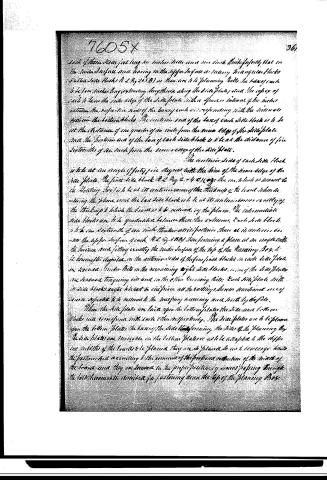
Each of these side blocks being six inches from each other, their upper faces on the inner surface and having on the upper surface as many triangular blocks (called side blocks A 2 by 2 by 3 B) as there are to be planing bolts, the base of each to be four inches long extending lengthwise along the side plates, and the edges of each to have the outer edge of the side plate with a space or interval of two inches between the respective ends of the bases of each, corresponding with the intervals between the bottom blocks. The anterior end of the base of each side block is to be at the distance of one quarter of an inch from the inner edge of the side plate, and the posterior end of the base of each side block is to be at the distance of five sixteenths of an inch from the inner edge of the side plate.
The anterior sides of each side block is to be at an angle of forty-five degrees with the line of the inner edge of the side plate. The first side block A 2 by 2 by 4 C) (fig. 1) has one side in contact to the planing box, is to be at its anterior corner of the thickness of the board when drawing the plane, and the last side block is to be at its anterior corner exactly of the thickness to which the board is to be reduced, by the plane. The intermediate side blocks are to be graduated between these two extremes. Each side block is to be one sixteenth of an inch thicker at its posterior than at its anterior corner. The upper surface of each A 2 by 3 B) then forming a plane at an angle with the inner and fitting exactly the inner surface of the top of the planing box, to be inserted, the planing box, in the anterior sides of the four front blocks in each side plate, or screwed. Under-bits in the remaining eight side blocks, so that the side plates are screwed, tangency bits and in the other grooving bits. Each side plate with its side blocks ought to be set in the piece all the castings shown mentioned, and of course expected to be reduced to the necessary accuracy and finish by the file.
Then the side plates are laid upon the bottom plates, the side and bottom blocks will correspond with each other respectively. The side plates are to be placed upon the bottom plates the bases of the side blocks forming the sides of the planing box. The side plates are inserted in the bottom plates so as to be adapted to the different widths of the boards to be planed, they are to be placed so as to converge towards the posterior and according to the amount of the proposed reduction of the width of the board and they are secured in the proper position by screws passing through the bolt-holes in the described for fastening down the top of the planing box.
Page 6.
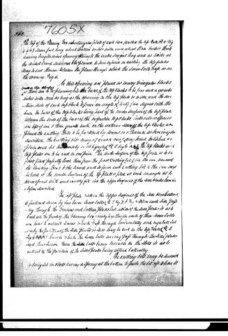
The top of the Planing Box is a rectangular plate of cast iron (called the top plate, Fig 4 & 5) seven feet long, about fourteen inches wide, and about three inches thick, having longitudinal openings through the centre six feet long and as wide as the widest face of the planer, to save expense in casting the top plates may be cast thinner between the places through which the Screw-bolt Tops, as in the Planing Fig 6.
In this opening are placed as many triangular blocks (called Top Blocks) as there are to be planing bits. The bases of the top blocks to be four and a quarter inches wide and as long as the opening in the top plate is wide, and the two thin sides of each top block to form an angle of forty-five degrees with the base, the bases of the top blocks being part of the under surface of the top plate. Between the lines of the bases of the respective top blocks, intervals or spaces are left of one and three quarters inch. On the centres sides of the top blocks are placed the cutting bits to be fastened by screws as otherwise as hereinafter described. The cutting bits may of course be of any kind polished or plain and set horizontally or obliquely (Fig 2, Fig 4 & 5). The top blocks and top plates are to be cast in one piece. The under surface of the top plate is to be first filed perfectly true, then from the first cutting bit (see the one, nearest the Planing Box) to the lowest, each cutting bit to the one next behind it, the under surface of the top plate is filed at such an angle as to correspond with and exactly fit into the upper surfaces of the side blocks hereinbefore described.
The top plate rests on the upper surfaces of the side blocks and is fastened down by two large Screw-bolts (Fig 2, Fig 7, & Fig 8) in each side, passing through the thickness and bottom plates but above of the side plates so as to limit all the parts of the Planing Box rigidly together. In each of these Screw-bolts are holes to admit screws which pass through horizontally and regulate laterally the position of the side plates so that they may be set in the top plate (Fig 2, Fig 4 & 5) through which the Screw-bolts moving pass through the side plates and thus secure them. The bolt being inserted in the slots so as to admit of the position of the side plates being altered laterally.
The cutting bits may be secured by being set in slots having a spring at the bottom to push them up where it
Page 7.
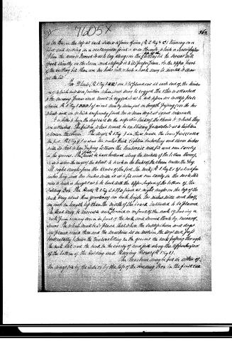
is to be, in the top at each place a piece of iron (R 2 Fig 5 C) turning on a short and cutting in a rectangular joint to arm through which a screw passes. When the arms turned so as to lay along on the cutting, the screws will operate directly on the same and depress it in its proper place. In the upper part of the cutting box there are the holes into which a work may be inserted to draw out the bit.
The Wheels (R 1 Fig 1 BD) are to be placed one at each end of the machine, in which are two friction wheels, and they are to be coupled the latter is attached to the moving frame, and must be coupled so as to act upon an endless piece of chain (R 1 Fig 1 DDD) of about twenty inches in length passing over the two wheels and in which are firmly fixed two or three dogs at equal intervals.
It is better to have the dogs cut in the respective links of the chain so that they are attached. The friction wheel must be an sliding pedestal so as to lighten a loose machine. The dogs (R 1 Fig 1) are three inches the lower part (called the foot R 1 Fig 4) is about two inches thick eight inches long and three inches wide so that when passing between the tractors it will fit and run easily in the grooves. The head is cast hollowed along the middle of the bottom thereof, so as to allow the ends of the wheel to work in the links of the chain under the dog.
At right angles from the center of the foot, the neck (R 1 Fig 2 3) is cut four inches long and five inches wide so as to fit and run easily in the neck. The pins in such a height as to be level with the upper surface of the bottom of the holding box. The head (R 1 Fig 2 3) is fixed at right angles in the top of the neck being about three quarters of an inch high. The necks wide and long, as such in length as than the middle of the lower intended to be placed. The head may be increased and formed in the form of the neck by having a neck piece coming down in front of the neck and turned there by means of screws. The wheel must be placed that when the endless chain and dogs are placed under them and the machine set in motion, the dogs will pass horizontally between the tractors fitting in the grooves, the neck passing through the neck slot and the head in the cavity of the box just along the upper surface of the bottom of the holding and Raising Box (R 1 Fig 1).
The machine may be set in either of the ways viz by the sides or by the top of the Holding Box in the first case
Page 8.
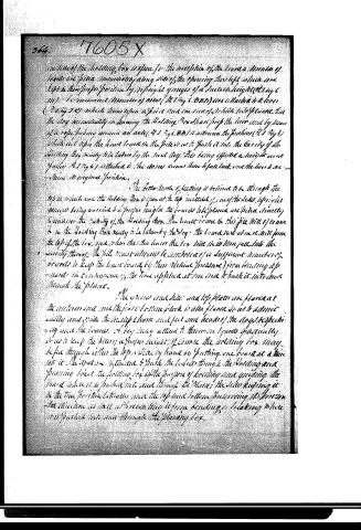
one side of the Holding Box is open for the reception of the board a number of boards are piled immediately along side of the opening thus left which are kept in their proper position by upright grooves of a suitable height (Fig 6 and 11). A convenient number of arms (Fig 6, 8, 11) are attached to a lever (Fig 1, 8) which turns upon a pivot and one end of which is placed that the dog immediately on leaving the Holding Box shall push the lever and by means of a rope passing around an axle (Fig 6, 8, 11) to advance the pusher (Fig 3) which act upon the board as the pile is set to push it into the cavity of the Holding Box ready to be taken by the next dog. This being effected a suitable cover (Fig 6) is attached to the arms so as to fall back and the lever is returned to its original position.
The better mode of feeding is believed to be through the top so that when the Holding Box is open at the top instead of one of the sides, the pile of boards being carried to a proper height the boards to be placed are piled directly to cover the cavity of the Holding Box. The board to be fed is the pile will be covered by in the Holding Box ready to be taken by the dog. The board next above it will form the top of the box, and when the dog leaves the box will in its turn fall into the cavity thereof. The pile must always be composed of a sufficient number of boards to keep the board (and by their vertical pressure) from heaving up wards in consequence of the force applied at one end to push it into and through the plane.
The grooves and side and top plates are formed at the anterior end and the first bottom block is also formed so as to admit easily and wide the top plane and feet and heads of the dogs respectively and the boards. A boy may attend to these on boards gradually so as to keep the pile of a proper height, of course the holding box may be fed through either the top or side by hand by putting one board at a time into it. The dogs are intended to push the board through the Holding and opening box. The holding box is the purpose of holding and guiding the board while it is pushed into and through the plane; the side keeping it in the true position laterally and the top and bottom preventing its heaving in the direction as well as preventing it from bending or breaking while it is pushed into and through the planing box.
Page 9.
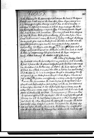
In the planing for the desired object will reduce the board to the required thickness and width and at the same time plane, tongue and groove it by taking off successive shavings each so thin as not to occasion inconvenience to difficult to overcome or which may endanger the bits or other parts of the machinery or require them to be made of greater strength than may be done with convenience. Were one of course to no inaccuracy the laying the precise thickness of each shaving. The practice so far I have found it convenient to reduce the board by passing it through the planing box one quarter of an inch in thickness and the same in width and the description given above is of a machine constructed for such a reduction. Each cutting bit therefore will take off only forty-eighth of an inch in thickness; each jointed bit at one thirty-second width of an inch in width. In knowing and governing bits of course made the tongue and groove merely without reducing the absolute width of the board.
The bottom of the planing box being horizontal when the last cutting bit is one quarter of an inch less than the first it follows that the general inclination of the top plate is downwards from the anterior to the posterior end. If therefore the mean surface of the top plate were a plane, it would follow that in passing from each cutting bit to the next one the board would be forced through a diminishing curve not equal to its own thickness and a through which therefore it could not pass without great friction and difficulty and being actually constructed to avoid this inconvenience the mean surface of the top plate is but upwards and backwards from each cutting bit to the one next behind it as herebefore described so that the part of the surface between every two cutting bits forms an obverse angle to the one form most with the horizon by the general inclination of the top plate. The consequence of this was a simple and expedient applied to the side blocks is that the board passes through the planing box with the least possible friction and without touching any part except the bottom through and the edges of the same. So the wheels and molly chain being put in motion it is evident that the first dog now act upon the side of the board in the hollow box and produce clear through that side the planing box, as soon as the board has left
Page 10.
No. 1605 X
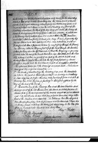
The holding key and the board is supplied and ready for the next log which is then about to enter the holding box. The plane must of course operate with perfect accuracy when properly constructed and used; it is however important not to strain or run the risk of breaking any part of the machinery. Sometimes the head of the dog may get under the end of the board in consequence of its being split or otherwise defective, in which case if the planing key be pulled down it is without effect on the machine must stop, or that some part of it must give way. It may frequently happen also that a board will have to be more reduced in width or thickness so that there is prepared to be done by one passing through the planing box. It is my intention therefore first to pass the board through the machine without fastening down the top plate and without the tangery or grooving iron and when the end of the board shall have been thus tested and the iron stuff reduced to within one quarter of an inch of the desired width and thickness then to it pass it through with the top plate fastened by screws, springs or weights until the machine arranged as heretofore described.
The references herein are to the drawings annexed hereto. I declare as now and my original invention ---
1. The mode of constructing the holding key and the machine in which the board is therein prevented from bending or breaking is showing from its proper direction and free ingress given to it into the planing box while the force for pushing it through is applied by the dog at the tail of the board.
2. The construction of the Planing Box and the combination and arrangement of the bars thereon and the mode in which friction is diminished by the arrangement of the reverse angles as at c c d e f g h and i k is not claimed as new and my original invention may otherwise part of the machine also described. In testimony that the above is a true specification of my said improvement as aforesaid I have hereunto set my hand and seal the twenty-fifth day of May in the Year of our Lord one thousand eight hundred and thirty-three.
Benj. Higginson
To: Mr. M. M. M. M. M. M. M. M. …
Published accounts: journal notice
Notice in the monthly list of patents, with remarks
Journal of the Franklin Institute, new ser., vol. 12 (1833), p. 394 · View the page
3. For a Planing Machine; Benjamin Kugler, city of Philadelphia, June 3.
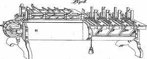
Remarks. The machinery here patented is described with much care and minuteness, and the parts of which it is constituted are represented by a number of plans, sections, and perspective drawings, without which a clear idea of it cannot be conveyed; its general action is as followsThe plane, which is of metal, is firmly fixed, and is provided with a number of irons, placed one behind the other; the first of these is set rank, to operate as a jack plane, and the succeeding ones have different degrees of hold. Irons intended for grooving are also set edgewise, in the same metallic plane. In the drawing, six irons are represented, one behind the other. The board to be planed is drawn, or rather driven, through the machine, under the plane irons. This is effected by means of an "endless plate chain," which passes round cog wheels at each end of the machine; upon the top of this plate chain the boards are to be placed, and by it they are carried under the planing, and between the grooving irons. There are proper fixtures for preventing the springing of the board, and for various other purposes, many of which being considered as mere matters of arrangement, are not claimed by the patentee. The things claimed are "the holding box, and the machine in which the board is prevented from bending, breaking, or swerving from its proper direction, and free ingress given to it into the planing box, while the force for pushing it through is applied to the dog at the end of the board. The construction of the planing box, and the combination and arrangement of the bits therein, and the mode in which the friction is diminished by the arrangement of the reverse angles." We are not informed respecting the final success of this machine, but we know that it has been put up with much care and at great expense. The main difficulty which presents itself to us is one which we have before had occasion to express in relation to planing machines with a large number of irons acting simultaneously on a great width of surface; it seems to us that the resistance to be overcome is too great, especially when boards are hard, crossgrained, and knotty. The hand humours such boards, but the machine waits not to accommodate its customers, according to their different dispositions, but treats all alike. The patentee we know to be a gentleman of much ingenuity and perseverance, and we shall be gratified to hear that these attributes have enabled him in this case to triumph over all difficulties.
DATAMP: illustration
Illustrations from DATAMP

DATAMP (Directory of American Tool and Machinery Patents), via the Internet Archive · Archived DATAMP page
About this record
- Patentee
- DATAMP
- Date
- the Name and Date index of patents, DATAMP, USPTO records
- Invention
- DATAMP
- Listed in
- the Name and Date index of patents, DATAMP, USPTO records, Jim Shaw's X-patent list, the Journal of the Franklin Institute, Burke's List of Patents (1847)
- Burke's 1847 Patent Office list gives the same patent.