

Drawings and documents
National Archives restored drawings: drawing
S.S. Allen's Patent Drawing for Horse Power

National Archives, Restored Patent Drawings (Record Group 241) · Full-size scan at the National Archives · Catalog record
Show the text on the drawing Hide (36 words)
Words on the drawing as machine-read by the National Archives; not checked. Useful mainly for searching.
74. MECHANICAL Dn / Lorse / 185 Mechanical Motors; / Gears. / Hoss / S.S, ALLEN'S / HORSE POWER. / CLASSIFICATION / Patented 29 June 1833. / 7609- + / DIVISION. / OIR / WE
USPTO scan
The patent as scanned by the USPTO
-
 Page 1
-
 Page 2
-
 Page 3
-
 Page 4


U.S. Patent and Trademark Office · Google Patents
Show the transcription Hide (1,052 words)
Machine transcription (LightOnOCR) of the pages as scanned by the USPTO, most of them the handwritten copies made when the records were restored after the 1836 fire. Not checked; it can misread handwriting, so compare it with the scan.
Page 1.
7609X
S. S. Allen,
Horse Power.
Patented June 29, 1833.
AM. PHOTO-LITHO. CO. N.Y. (OSBORNE'S PROCESS)
Page 2.
June 29, 1833
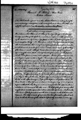
Samuel H. Allen's Horse Power
Letters Patent
The Schedule referred to in these Letters Patent and making part of the same containing a description in the words of the said Samuel H. Allen himself of his improvement in the machine called a Horse Power.
To all whom it may concern:
Be it known that Samuel H. Allen of Saratoga Springs in the County of Saratoga and State of New York have invented an improvement in constructing the machine usually called a horse power and that the following is a full and exact description thereof. The Horse power which I employ is intended to be portable. It is constructed that it may be readily transported from one place to another, and which removes its motion from a lever, or sweep, or iron moved by the walking of the horse, in a circle, although I do not intend to confine myself to any precise size in any of the various parts. Still for the sake of description, give the proportions which I have found to answer well in practice.
Make a frame or box about six feet long and fifteen inches in height. The end pieces of 4 inch plank, three feet long at their lower edges, and two feet 8 inches at their upper. The sides three feet long in about two inches. The sides may be of two inch plank and must be securely fastened to the ends. This box is to contain the driving wheels and gears on three vertical shafts, running in suitable boxes, to receive these boxes and contain the shafts, pieces of timber is to run along the upper and lower sides of the box. The upper pieces may be 3 by 8 inches flush with the side and under and beyond through the ends, but of its edges must reach just to the center of the box, as the upper bearings or boxes of the shafts are to be fastened there. The lower timber is three by nine inches and twelve feet long, as it is to support the box without the box being secured to one end of it like the upper timber and notched in, and secured to the other end. The shaft of the first driving wheel may be about 4 inches square and extend above the top timber about 6 inches, where it is a little to form to receive the lever or sweep, to which the horse is to be ganged. This shaft is made of cast iron and has a flat within a flanch and moves, to which the arms of the wheels, to be presently described, are secured.
Page 3.
The wheel is about thirty in diameter and stands near to the lower end of the shaft. The second driving wheel is about 26 inches in diameter, it stands above the first driving wheel, and has on its shaft a pinion of about one fourth of the size of the first wheel, which meshes into it. The third shaft has a pinion of about one fifth of the size of the second wheel, which meshes into it. On the lower end of this third shaft, there is a bevel or oblique wheel, which may be about 24 inches in diameter, its teeth perfect downwards, and mesh into a pinion about one fifth of its size. The pinion is fixed upon an iron shaft, which runs horizontally, near to the ground, and extends along the lower timber, six feet without the boy, or frame (and carries on its extreme end a wheel of eighteen inches in diameter, from which a band extends to a threshing machine, small gins mill, or any other machinery to which such a horse power is adapted. To receive this horizontal shaft, the edge of the sill, or projecting piece of timber is rebated, or hollowed out on its under side, by which means it is protected from injury by the feet of the horse, or from any other cause. Instead of making the lower or sill timber, in one piece, it may be made to unship near to the boy, and be removed along with the horizontal shaft, when required. The wheels before named, consist of cast iron rims with arms made of wood. These arms are formed of two pieces of hard stuff or yew, hinged together in the middle, the timber should be about 3 by 3 inches. The shaft passes through a mortise in the centre of the arms, and they are secured by bolts to the flanches, or disks, upon the shafts, the ends of the arms may then be turned off to fit the inner part of the rim of the wheel, the rims are strengthened by a flanch which projects inwards serving as a bearing for the arms (and also to bolt them to, a projection is cast on each side of the arms, within the rims to confine them in width, and secure them from splitting, when the horse power is to be used, it is placed upon the ground, in which it will be easy to make a small excavation to receive the lower part of the wheel. Four stakes are to be driven into the ground at the four corners of the boy, and two chains lightened on these by means of toggles, passing over the boy, one at each end, will render it perfectly secure. What I claim as new and my invention, is the manner of making the wheel, as before described.
Page 4.
6/29/1833 7609x
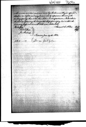
with wooden arms and cast iron rims, by which means they are affixed, cheaper, are lighter and may be more easily repaired in the case of the breaking of a cog, than when the whole is made of cast iron. I also claim the manner of securing the horizontal shaft from injury, (and so that the horse may pass over it with little or no obstruction).
Witnesses:
Thos. P. Jones
Jos. Amory
Samuel S. Allen
Patented June 29th 1833.
1020 3-2-33 (Dr. in post folio)
Published accounts: journal notice
Notice in the monthly list of patents, with remarks
Journal of the Franklin Institute, new ser., vol. 12 (1833), p. 399 · View the page
13. For a Portable Horse Power; Samuel Allen, Saratoga Springs, Saratoga county, New York, June 29.
Remarks. This machine, like most of the portable horse powers, has the gearing of wheel work below the lever, or sweep, to which the horse is to be attached. There are three wheels and three pinions, upon suitable shafts; the last shaft being a horizontal one, and passing along close to the ground, where it is boxed, or covered, to prevent injury from the feet of the horses; at its extreme end it has a whirl, from which a band is to extend to operate upon any machinery. The main point claimed is the mode of making the wheels, which are to consist of iron rims, with arms of wood. The iron rims are to be strengthened by a flanch, which projects inwards, and serves also as a bearing for the wooden arms.
About this record
- Patentee
- DATAMP
- Date
- the Name and Date index of patents, DATAMP, USPTO records
- Invention
- DATAMP
- Listed in
- the Name and Date index of patents, DATAMP, USPTO records, Jim Shaw's X-patent list, the Journal of the Franklin Institute, Burke's List of Patents (1847)
- Burke's 1847 Patent Office list gives the same patent.