

Drawings and documents
National Archives restored drawings: drawing
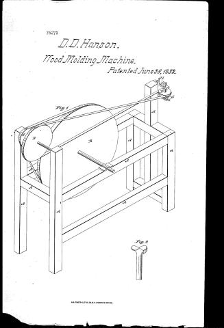
David D. Hanson's Patent Drawing for a Grooving Machine

National Archives, Restored Patent Drawings (Record Group 241) · Full-size scan at the National Archives · Catalog record
Show the text on the drawing Hide (133 words)
Words on the drawing as machine-read by the National Archives; not checked. Useful mainly for searching.
Cavid D. Hanson / Vol. 16.7. 251. / 144. WOOD WORKING MACHINES. / Molding, Hand Feed. / W Grooving June th Machine, planing mc / $1 Jane 29. 1833 / atented 1 29. 1833, / CLASSIFICATION / Fif.1. / 7627+ / DIVISION. / Fight, / The catter or groover, made of / cast steel has two spiral enger / winding halfround, with an edge / at the tor, the length of its / diameter made crotched, or / resembling in form a swablow / tail, cutting at the a WI th / its upper and lateral edges ") / References; / Patent Offin / Fid. 1. Isometrical view. Fir2 cutterdeta ched / D, A.A. eight frame. inch pulley, B.principal E. whiten spendle pulley. F. Made under the direction of the Commision of / G. anus. H. bearing. I gague / Patuts in conforminty with Oct floorgreps 3 March 1837, / nh / Commifination if Patents,
USPTO scan
The patent as scanned by the USPTO
-
 Page 1
-
 Page 2
-
 Page 3
-
 Page 4


U.S. Patent and Trademark Office · Google Patents
Show the transcription Hide (1,083 words)
Machine transcription (LightOnOCR) of the pages as scanned by the USPTO, most of them the handwritten copies made when the records were restored after the 1836 fire. Not checked; it can misread handwriting, so compare it with the scan.
Page 1.
7627X
D.D. Hanson,
Wood Molding Machine.
Patented June 29, 1833.
Fig. 1
Fig. 2
A.M. PHOTO-LITHO. CO. N.Y. (OSBORNE'S PROCESS)
Page 2.
7627x
June 29, 1833 257
David D. Hanson of Ware in the State of New Hampshire
Letters Patent.
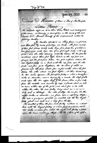
The schedule referred to in these Letters Patent and making part of the same, containing a description in the words of the said David D. Hanson himself of his improvement called the growing Machine —
This Machine operates in an oblong frame one foot wide and three feet long by means of pulleys and bands. The frame consists of two foot pieces twenty inches long, five posts, two of which are two feet eight inches high, two of one foot eight inches with a cap-piece, and the other standing centrally between the two posts last mentioned about three feet high, halved on the cap-piece and passed into the foot-piece below, one girt crosswise between the two highest posts, on a level with the cap-piece upon the other posts, and four girts lengthwise, the two lower of which are passed into the posts about four or five inches above the foot-pieces, the other about one foot higher, all these timbers may be two inches square. The principal pulley or wheel is twenty-four inches in diameter, and is moved by a crank, the shaft of which rests upon the two upper long girts of the frame, three or four inches from the middle and secured by caps, is placed about one inch or more within one of the girts, and about five or six inches within the other the said pulley being about one or two and a half inch in thickness. Two other pulleys, the one four and the other eight inches in diameter, are fixed upon a revolving shaft, the ends or quadrants of which are inserted into the two longest posts about one inch and a half from the top.
The smallest of these, the four inch pulley is placed in a direct line with the largest pulley or wheel first mentioned, about two inches or more from which the eight inch pulley is placed upon the same revolving shaft, — to the exterior of the fifth or
Page 3.
7627x June 29, 1833
232
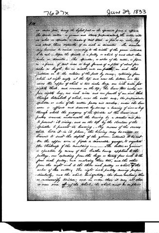
or centre post, being the highest part in the apparatus frame is affixed the final cutter or groover and stands perpendicularly, the cutter with its arbor or spindle is made of cast steel is five or six inches long and about three tenths of an inch in diameter. The diameter may however be varied according to the width of the groove intended to be cut. Upon the spindle is a pulley or whir of wood about three inches in diameter. This spindle, or arbor of the cutter, is fixed in a frame of cast iron or brass formed of a plate of about five inches in length, two in width, and one fourth of an inch thick fastened on to the outside of the posts by screws. Extending from which at right angles at the top and near the bottom, are two arms, the upper of which is two inches long, one inch wide, five eighths thick, and rounded on the top; the lower two inches and five eighths long, one inch wide and one fourth of an inch thick through holes both of which, near the outer end, the perpendicular spindle or arbor of the cutter passes and revolves. Under the lower arm is affixed and secured by screws a bearing of iron or brass through which the gearing of the spindle at the lower end passes, secured underneath the bearing by a washer and pin to prevent its rising, and on the top by the shoulder of the spindle to prevent its lowering. By means of the screws which hold it in its place, the bearing may be raised or lowered to suit the depth of the groove intended to be cut. On the upper arm is fixed a moveable gauge, to regulate the thickness of the moulding. The cutter or groover is operated by means of two leather bands applied to the pulleys, one extending from the large or twenty-four inch to the four inch pulley, and enclosing them two, and the other from the eight inch to the three inch pulley or whir of the arbor of the cutting. The eight-inch pulley moving perpendicularly, and the whir horizontally, the bands enclosing them is necessarily twisted, and in order that it may not slip or run from off of the whir, the whir must be so placed
Page 4.
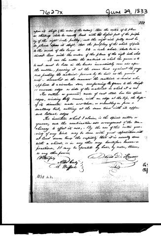
upon its shaft (the arbor of the cutter) that the center of its plane or thickness shall be exactly level with the highest part of the periphery of the eight-inch pulley, and the eight-inch pulley must be so placed upon its shaft, that the periphery of the wheel opposite to the crank of the large or 24-inch wheel shall be in a direct line with the center of the plane of the eight-inch wheel.
To use the cutter, the material in which the groove is to be cut must be held in the hands immediately over and upon the cutter, pressing it at the same time against the gauge and pushing the material forward by the hand as the groover cuts—somewhat in the manner the material is moved when applied to a circular saw, conforming the groove to the straight or curved edge or side of the material in which it is cut.
The cutter or groover, made of cast steel, has two spiral edges, winding half round, with an edge at the top, the length of its diameter made crooked, or resembling in form a swallow's tail, cutting at the same time with its upper and lateral edges.
The invention which I claim, is the spiral cutter or groover, and the combination and arrangement of the machinery to effect its use. By the use of this cutter grooving of any kind may be done with great expedition, with at least seven times the rapidity that it is usually done with a chisel, or in any other way heretofore known or practiced. It may be operated by hand, by water, steam, or any other power.
Witnesses:
A. H. Brady
A. Wofford
David D. Hanes
1050 lbs.
Published accounts: journal notice
Notice in the monthly list of patents, with remarks
Journal of the Franklin Institute, new ser., vol. 12 (1833), p. 403 · View the page
25. For a Grooving Machine to form the Grooves for Pannels, either in straight, or in curved work; David H. Hanson, Weare, Hillsborough county, New Hampshire, June 29.
Remarks. The grooving is to be effected by a cutter, which stands out from the end of a vertical spindle, running in collars, and made to revolve by means of whirls and bands. The cutter operates something like a drill, or auger, having edges on its end and its two sides; its diameter must be equal to the width of the groove to be cut: there are rests or guides to direct the stuff, which is held in the hands, so that whether curved or straight, by forcing the stuff on, the groove shall be regularly cut. This machine, it is said, works at least seven times as rapidly as any one previously used for the purpose. The claim is to "the spiral cutter, or groover, and the combination or arrangement of the machinery to effect its use." The combination of the machinery has nothing in it new, or necessary to the action of the cutter, as other, and better arrangements, may be easily made; this, however, will not affect the use of the cutter. The size and construction of a frame for sustaining the apparatus is given with all the minuteness which might be required in mathematical admeasurement, whilst they are things which every workman would make equally well, although deviating in every particular from the directions given.
DATAMP: illustration
Illustrations from DATAMP
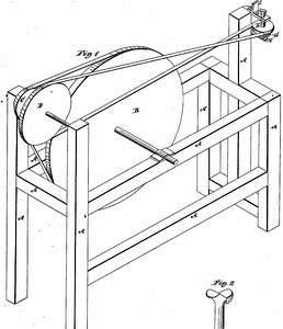

DATAMP (Directory of American Tool and Machinery Patents), via the Internet Archive · Archived DATAMP page
About this record
- Patentee
- DATAMP
- Date
- DATAMP, USPTO records, Burke's List of Patents (1847)
- Invention
- DATAMP
- Listed in
- the Name and Date index of patents, DATAMP, USPTO records, Jim Shaw's X-patent list, the Journal of the Franklin Institute, Burke's List of Patents (1847)
- The sources give different dates; the date shown is the one most of them agree on.
- The Franklin Institute's journal confirms the date shown.
- Burke's 1847 Patent Office list gives the same patent.