

Drawings and documents
National Archives restored drawings: drawing
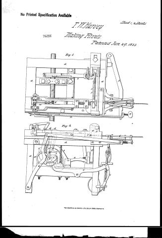
T.W. Harvey's Patent Drawing for a Machine for Making Rivets


National Archives, Restored Patent Drawings (Record Group 241) · Full-size scan at the National Archives · Catalog record
Show the text on the drawing Hide (57 words)
Words on the drawing as machine-read by the National Archives; not checked. Useful mainly for searching.
Sheet 1. 10. METAL WORKING, / Bolts and Rivets, Making. / T.W. HARVEY'S / 14" / Making. / CLASSI ICATION / Patented 29th June 1833X / 7629 X / MACHINE FOR MAKING RIVET S. / DIVISION. / Fig.1. / PLAN. / Fig.2. / SIDE ELEVATION
Sheet 2. LASSIFICATION / 7629.x / DIVISION / END ELEVATION. / Fig. 3. / eip / Fig, 4. / E,
USPTO scan
The patent as scanned by the USPTO
-
 Page 1
-
 Page 2
-
 Page 3
-
 Page 4
-
 Page 5
-
 Page 6


U.S. Patent and Trademark Office · Google Patents
Show the transcription Hide (1,504 words)
Machine transcription (LightOnOCR) of the pages as scanned by the USPTO, most of them the handwritten copies made when the records were restored after the 1836 fire. Not checked; it can misread handwriting, so compare it with the scan.
Page 1.
No Printed Specification Available
T. M. Harvey
7629X Making Rivets
Patented Jun. 29, 1883
Sheet 1, 2 Sheets.
Fig. 1.
Fig. 2.
THE GRAPHIC CO. PHOTO-LITH. 39 & 41 PARK PLACE, N.Y.
Page 2.
7629X.
T. W. Harvey
Making Rivets.
Patented Jun. 29, 1833.
Sheet 2, 2 Sheets.
Fig. 3.
Fig. 4.
THE GRAPHIC CO. PHOTO-LITH. 39 & 41 PARK PLACE, N.Y.
Page 3.
6/29/1833 7629X
June 29, 1833
Thomas H. Harvey
Letter Patent
The Schedule referred to in this Letter Patent and making part of the same containing a description in the words of the said Thomas H. Harvey himself of his improvement in the machine for making nails, heading wires & other similar purposes.
To all whom it may concern: You it known that T. H. Harvey have invented certain improvements in the machinery for making nails for Steam Engine Boilers and for other purposes, and which is also applicable to the heading of wood screws, bolts and other articles upon which heads are to be formed by pressure. And I do hereby declare that the following is a full and exact description thereof.
In the accompanying drawings, AA represents the frame of the machine. The shaft B is that to which the driving power is applied, and which operates by means of gears on the other parts of the machine. The coupling C is for purposes to be presently described.
The iron or rod upon which the head is to be formed is fed into the machine by the feeding gear CC, which are represented as holding it. The iron or rod passes through the head D and is seized and held fast in the jaws EE working on a joint at top. When firmly embraced between these jaws, the iron is made to advance upon the portion which projects within the jaws, and thus form the head. The setting of the shank of the nail is effected by the rotation of the screws, a lateral motion being given to them for that purpose. Upon the inner side of the head D there is a slot made through which the wire or rod passes, which slot constitutes one part of the cutter. The dies in the class are of such thickness as correspond with the length of the shank of the nail, and as soon as the head is formed by the heading die and becomes released, the shank rotates and act off the wire by their action, or rather by that of the dies against the iron named slot &c.
The action of the arms respectively is as follows: When a bolt in the drawing which under the arrangement represents the head upon the shaft D moves to disengage the toggle joint.
Page 4.
by which the heading die is forced forward. Thus it effects by acting upon the moving piece D which is attached by a pivot or joint to the main toggle joint GG. The greater part of which as seen in Fig 2, is represented by dotted lines as in the actual machine it is hidden by other parts. Upon this cam (c to l) it usually forms a tongue which falls into a slot made to receive in the movable lever B. The tongue is seen at H fig 2 V moves by tension against the piece T, to keep the cam in its place whilst its action is against. The socket S of the heading die works then into the slider, the die X being usually keyed on with double keys D D, but it may sometimes be merely dropped into the place. The cam c to D, which is the lower end of the shaft B, serves to bring the toggle joint GG back which it does by acting upon the cam lever N which has an oblique end a round pin O against which the cam rests. The upper end of the lever is attached to one of the arms of the main toggle joint. The socket of the heading die may be connected to the toggle joint and retracted in various ways. I have sometimes done this in the way shown in the drawing by the aid of the small shaft P and the lever and slides connected with it, which are acted upon by the motion of the main toggle joint, but as every competent workman can devise means of doing this I do not intend in general to follow this arrangement I shall not here particularize it. Cam c to D acts against the lever Q which draws back the rod B and with it the feeding grab CC. These grabs are attached to the lever S by their under sides and by means of the screw T. The feeding is regulated with the almost precision. Cam c to D acts upon the lever U this connects at one end by means of a joint to the rod V, which by another joint at its opposite end carries the roller W Fig 3 which is a front view of the machine. This roller elevates and depresses the pointed rod X which when drawn down straight on the levers XX, and draws the grabbing jaws. The elevation of these levers serving to open them. Z is a spring which bearing upon the strokes a, a, draws the levers XX down when the cam which elevates them is not in action. Cams d & e serve to elevate and depress the levers b b b. Figs 1 & 2 when fulcrum is at E the two arches ends of the lever being
Page 5.
respect by them comes respectively, from the lever C, a fulcrum near the end of C, fig 1, connected with with the shaft D, on which also there is a crank E which works the rod or bar b, b' b" b" and forms a - in so doing vibrates the shears B, in a way which may be distinctly seen in fig 4. By being the point on which the vibration takes place and which serves to set off the area or not as before described. The jointed rod L, by the vibration of the bar f, opens and closes the jaws of the shears. This it effects by means of the toggle joints, it will be obvious from inspection of the drawing. "y" are the size of the parts the rod. The machine will of course vary in size according to the nature of the work it is intended to perform. In the annexed drawings it is shown of one half the actual size of the smallest machine which I contemplate making for use. I am adapted to work for steam boilers and similar objects I make a frame ten feet long, four feet wide and three feet ten inches high. The main toggle joint being three feet long, and vibrating on a centre one and a half inches, using a plate of one inch & a half to the heading bar. The shears it makes to vibrate two and a half inches. In the foregoing description I have followed the arrangement made in the parts of a machine which I have actually constructed. I have a made other which operate upon the same principle & in no part substantially the same, all differing from it in minor points of mere detail. The number of cams upon the main shaft may be increased or diminished, and the same reduction of the lever upon which they operate may be indefinitely varied, whilst the machine remains essentially the same. Most of the operating parts, which I have described and represented, are not when taken individually new, but I have so combined them as to give them a new & peculiar character & to produce an effect which is new and most useful. It is therefore upon the general arrangement and combination of the parts by which this machine is distinguished from all others which have been constructed for similar purposes, that I found my claim to a patent in the individual parts. However I claim the particular construction of the cam H, as described and represented. I also claim the arrange-
Page 6.
7629X
ment of the toggle joint by which the sheets are opened and closed, by the vibration of the bar marked f in the drawing. Having thus given a full description of my said machine, and having pointed out what I particularly claim as new herein; I am ready to the improvement of the use in such case made and provided. I will now add for the information of those who may construct & use the same, that as in the making of the large kind of sheets, the rods must be heated from one should be made for allowing water to run upon the dies to protect them from being ruptured.
Thomas M. Harvey.
For a patent date (1458 words)
Published accounts: journal notice
Notice in the monthly list of patents, with remarks
Journal of the Franklin Institute, new ser., vol. 12 (1833), p. 402 · View the page
23. For a Machine for making Rivets, Heading Screws, and performing other similar operations; Thomas W. Harvey, Jamestown, Chataque county, New York, June 29.
Remarks. This machine is too complex to admit of its being described in words, or even with drawings, without presenting a number of its parts separately. As it is intended for the making of large rivets, such as those used for tanks and steam engine boilers, which require considerable force in the formation of their heads by pressure, the movements for this purpose, as well as for cutting off the bars, are mostly effected by means of toggle joints. In making rivets of the smaller kind, heading screws, and other operations which do not require the upsetting of a large portion of metal, the wire, or rod, does not require to be heated; but for boiler rivets, this must be done, and on this account provision is made for allowing water to run upon the dies to prevent their being softened by the heat. The machine is described by references to the drawings throughout, and the specification concludes in the following manner, -" Most of the parts which I have described, and represented, are not, when taken individually, new; but I have so combined them as to give to the whole a peculiar character, and to produce an effect which is new and useful. It is therefore upon the general arrangement and combination of the parts by which this machine is distinguished from all others which have been constructed for similar purposes, that I found my claim to a patent. In the individual parts, however, I claim the particular construction of the cam No. 1, as described and represented. I also claim the arrangement of the toggle joint by which the shears are opened and closed by the vibration of the bar marked fin the drawing."
About this record
- Patentee
- DATAMP
- Date
- DATAMP, USPTO records
- Invention
- DATAMP
- Listed in
- the Name and Date index of patents, DATAMP, USPTO records, Jim Shaw's X-patent list, the Journal of the Franklin Institute, Burke's List of Patents (1847)
- The sources give different dates; the date shown is the one most of them agree on.
- The Franklin Institute's journal confirms the date shown.
- Burke's 1847 Patent Office list gives the same patent.