

Drawings and documents
USPTO scan
The patent as scanned by the USPTO
-
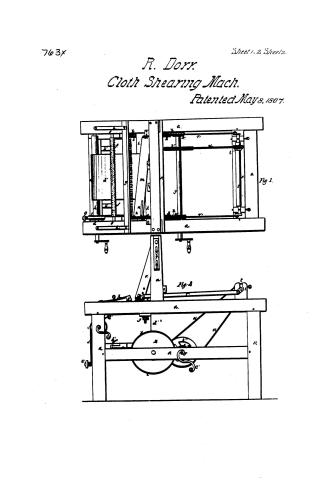 Page 1
-
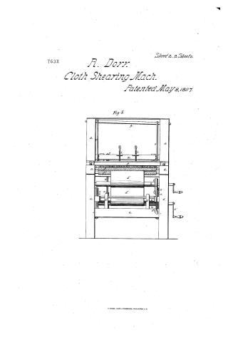 Page 2
-
 Page 3
-
 Page 4
-
 Page 5
-
 Page 6


U.S. Patent and Trademark Office · Google Patents
Show the transcription Hide (1,286 words)
Machine transcription (LightOnOCR) of the pages as scanned by the USPTO, most of them the handwritten copies made when the records were restored after the 1836 fire. Not checked; it can misread handwriting, so compare it with the scan.
Page 1.
763x
Sheet 1-2 Sheets.
R. Dorr.
Cloth Shearing Mach.
Patented May 8, 1807.
Fig. 1.
Fig. 2.
Page 2.
763X
Sheet 2-2 Sheets.
R. Dorr.
Cloth Shearing Mach.
Patented May 8, 1807.
Fig. 5.

Page 3.
The Claimants referred to in these Letters Patent and making part of the same containing a description in the annex of the said Royal Dow himself of a Machine for Shearing Cloth.
This machine consists of an exterior frame which supports the acting machinery, several rollers which aid the progress of the cloth under the shears and wheels or wheels for communicating motion. A Brush for raising the nap previous to its coming under the shears. A cushion which lifts the cloth to the level of the shears. A bed shear and a flying or movable shear. The frame in which the latter hangs, and the crank axis or bar or arms which move the flying shear. In particularly describing these several parts of the machine I will use the natural order in which they succeed each other in the operation of shearing, so far as is practicable and consistent with brevity. The exterior frame is constructed of wood or other proper material, elevated on feet high enough to allow space for the revolution of the wheels or wheels used in this machine.
The frame is so wide as to allow cloth of any required width to pass along within it. The horizontal bars support the axis of the several moving powers, and near the centre is an upright part connected at top in which hangs the frame of the flying shear. Near one extremity of this frame rests the beam on which the cloth to be sheared is rolled by means of a crank on the axis at one end thereof. In the same end of the axis is fixed a wheel crown which passes a strap that can be tightened at pleasure by means of a screw, to oppose resistance enough and stretch the cloth as it passes from the beam to the shears. Being drawn from this beam, the cloth passes between two rollers covered with card teeth, one of these teeth are in a contrary direction to the motion of the cloth. They oppose a uniform
Page 4.
743X
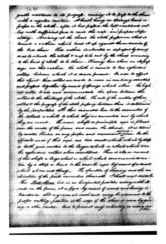
gentle resistance to its progress, causing it to pass to the shears with a regular motion. It is hung on springs, bears or presses on the cloth, after it has passed the last mentioned rollers with sufficient force to raise the nap, and prepare it for cutting). Straining at the shears the cloth passes over what is termed a cushion which bears it up against the underside of the base shears. This cushion is elevated or depressed by means so as to elevate the cloth & nap to be cut by the shears according to the kind of cloth to be sheared. Having been shown on its passage over this cushion, the cloth is carried to two cylindrical rollers, between which it is drawn forward. In order to effect this object these rollers are made to move in contrary directions and pressed together by means of springs which allow the highest roller to rise and accommodate the space between the rollers to the thickness of the cloth. The rate of the motion of these rollers & the progress of the cloth passing between them is determined by the proportions with their diameters bear to the diameters of the wheels or wheels to which they are connected and by which they are moved. The main shaft or principle axis is placed near the centre of the frame and under the shears. It is turned by water, horses, or any proper and convenient power. On the opposite ends of this axis, are two small wheels which by their teeth give motion to the larger wheels or wheels which turn the cylindrical rollers above mentioned. There is also on one end of this shaft a large wheel or wheel which communicates motion by a strap or band to the crank axis by means of a small wheel at one end thereof. The operation of shearing and the construction of the parts connected therewith I shall next describe. The Bed-shear lies in an horizontal position resting with its ends on the frame, it is fixed by means of screws and having a transverse slot or groove at each end may be advanced to the proper cutting position as the edge of the shears is worn by grinding or other causes. And to prevent any vibration or rising one
Page 5.
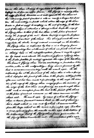
tion on this shear it may be regulated & kept down by means bearing on it from an upper frame. The flying or moving shear the edge of which traverses and cuts against the bed shear at their advancing point of contact is also in nearly a horizontal position; the counteracting or pivots which allow the edge of the shear to rise or fall as may be necessary in the act of cutting. To the heel end of this shear is attached a spring which keeps the edge of the flying shear to that of the bed shear at the place of contact during the progress of the cut. Besides keeping a regular pressure at the point of contact of the shears this spring prevents the wear & regulates the stroke to any casual unevenness in the bed shear.
The flying shear is suspended by bars or in a hanging frame from a connecting bar at the ends of which are pivots which rest on sliding boxes in the upright exterior frame & may be adjusted by screws and elevate the suspending frame & flying shear to the proper position for cutting against the edge of the bed shear.
This frame & flying shear has an oscillating or pendulum like motion when in the act of cutting, being drawn forward by the bars or arms communicating with the crank axis. In the suspending bar at the point end of the shear there is also a spring which depresses the point of the shear to the proper cutting position after one cut has been made & preparatory to the next. The direction of the edge of the flying shear varying from the direction of the edge of the bed shear and forming an acute angle there with cuts in succession from the heel to the point of the shears as the place of contact advances in the same manner as other shears act. The crank axis, by means of which the flying shear is drawn forward & comes back in the act of shearing has a small wheel on one end by which it receives motion from the large wheel on the main or principle axis. Two bars or arms extending from the cranks on this axis to the bottom of the suspending bars of the flying shear frame give motion to the flying shear & make the cut. The revolution of this axis
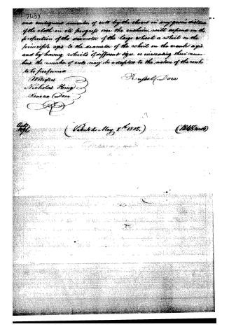
Page 6.
and consequent number of cuts by the shears in any given distance of the cloth in its progress over the surface, will depend on the proportion of the diameter of the large wheel or wheel on the principle axis to the diameter of the wheel on the crank axis and by having wheels of different sizes, or increasing their numbers, the number of cuts may be adapted to the nature of the work to be performed.
Witnesses
Nicholas King
Jonas Davis
Joseph Davis
Filed May 8th 1845.
(1845)
About this record
- Patentee
- Jim Shaw's X-patent list
- Date
- the Name and Date index of patents, USPTO records, Burke's List of Patents (1847)
- Invention
- the Name and Date index of patents
- Listed in
- the Name and Date index of patents, USPTO records, Jim Shaw's X-patent list, S. A. Elliot's printed list of patents, Burke's List of Patents (1847)
- The sources give different dates; the date shown is the one most of them agree on.
- S. A. Elliot's printed list of patents gives the same name and date.
- Burke's 1847 Patent Office list gives the same patent.