

Drawings and documents
National Archives restored drawings: drawing
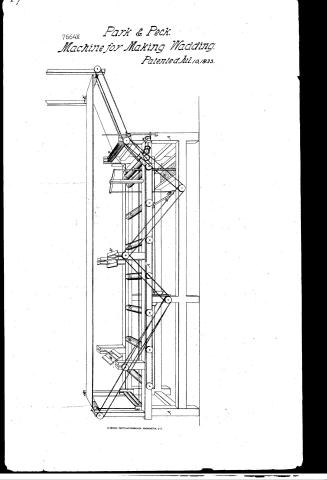
J. Park and W.S. Speck's Patent Drawing for a Machine for Cotton Wadding

National Archives, Restored Patent Drawings (Record Group 241) · Full-size scan at the National Archives · Catalog record
Show the text on the drawing Hide (64 words)
Words on the drawing as machine-read by the National Archives; not checked. Useful mainly for searching.
19. CARDING, / 28 Wadding / CLASSI ICATION / 7664 / DI ISION. / sding / J.PARK 8 W. S o PECK / rame / Cotton Wadding / Patented 10th July 1833. / prawing Rollers / sizing Rollers / Conveyers / hast / caring for sizing Rollers / its of sizing / Pamp / Upper Conveyers / of / rickland Del, / Pateat office / Made under the eter action of the commy
USPTO scan
The patent as scanned by the USPTO
-
 Page 1
-
 Page 2
-
 Page 3
-
 Page 4


U.S. Patent and Trademark Office · Google Patents
Show the transcription Hide (900 words)
Machine transcription (LightOnOCR) of the pages as scanned by the USPTO, most of them the handwritten copies made when the records were restored after the 1836 fire. Not checked; it can misread handwriting, so compare it with the scan.
Page 1.
7664X
Park & Peck.
Machine for Making Wadding.
Patented Jul. 10, 1833.
Page 2.
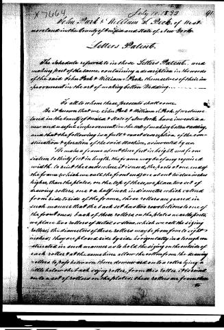
July 10, 1833
John Park & William H. Peck, of Westmoreland in the County of Onida and State of New York.
Letters Patent.
The schedule referred to in these Letters Patent, and making part of the same, containing a description in the words of the said John Park & William H. Peck, themselves of their improvement in the art of making cotton Wadding.
To all to whom these presents shall come.
Be it known that we John Park & William H. Peck, of Westmoreland in the County of Onida & State of New York, have invented a new and useful improvement in the art of making cotton Wadding, and that the following is a full & exact description, of the construction & operation of the said Machine, as invented by us.
We make a frame about three feet in height, and from sixteen to thirty feet in length. The frame may be of any required width, to suit the ends where it is used. The posts at one end of the frame (which we call the front end) are about twelve inches higher than the plates, on the top of these, we place two sets of drawing rollers, one & a half inch in diameter which extend from side to side of the frame, these rollers are geared in such manner that the back set has two revolutions to one of the front ones; back of these rollers, on the plates near the posts, we place two rollers of metal or stone, which we call the sizing rollers; the diameters of these rollers may be from four to eight inches; they are placed side by side horizontally in a trough constructed in such manner as to hold the sizing on the outside of each roller & at the same time allow the cotton from the drawing rollers to pass between them downward on to a roller lying a little below the back sizing roller, from this roller it is wind on to a set of rollers on the plates; these rollers are from three
Page 3.
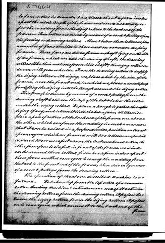
to four inches in diameter & are placed about eighteen inches apart the whole length of the frame and serve as a conveyor, for the wadding from the sizing rollers to the back end of the frame. These rollers are driven by means of a cord & pulleys from the feeding or drawing rollers. Above & below these rollers, we place a number of fans similar to those used on a common deep-joing frame. These fans are driven from a shaft lying on the side of the frame, which we call the driving shaft; the drawing rollers take their motions from this shaft; the sizing rollers are driven with gear wheels. From the drawing rollers to supply the sizing rollers with sizing, we place a tub by the side of the frame, near the front end, in which we place a small pump for lifting the sizing into the trough around the sizing rollers. This pump is driven by means of a cord & pulley from the drawing shaft between the top of the tub & below the roller under the sizing rollers. We place a trough to gather the surplus sizing if any, and return it into the tub again; we likewise place a pair of rollers at the back end of the frame one above the other, which confines the wadding in such a manner, that it can be raised in a perpendicular position on to a set of conveyors which are framed with two rollers, one of which is placed two or more feet above the last mentioned rollers, the other from four to six feet, in front of the frame, we wind cards around these rollers; from two to four inches apart these form another conveyor to convey the wadding from the back to the front end of the frame, then driven by means of a cord & pulleys from the drawing rollers.
The operation of the above described machine is as follows. We take a lap from the lap roller of a common cotton Carding Machine & introduce one end of it between the drawing rollers, from the drawing rollers, it passes between the sizing rollers, from the sizing rollers, it passes on to conveyors, which carries it to the back end of the frame.
Page 4.
frame, it is then raised nearly perpendicular onto another set of conveyors, which carries it to the front end again, while the wadding is passing from the front to the back, and from the back to the front end of the frame every other part of the machine is in operation.
What we claim as our invention or discovery consists in the applying and proportioning the above described machinery, generally & especially the passing the cotton between the drawing & sizing rollers in such a manner as to make a continued sheet which is sized and dried by the operation of the same machine.
Witnesses
Philo C. Lewis
E. P. Baumann
John Park
William H. Peck
(Patented 10 July 1853)
Drawing on Portfolio
By A.
N.Y.C.
Published accounts: journal notice
Notice in the monthly list of patents, with remarks
Journal of the Franklin Institute, new ser., vol. 13 (1834), p. 29 · View the page
8. For a Machine for making Cotton Wadding; John Park and William Peck, Westmoreland, Oneida county, New York, July 10.
Remarks. We are not familiar with the ordinary mode of making wadding, and cannot therefore compare the process as performed by this machine with that heretofore followed. As regards the machine itself, judging from the drawing, it appears to be well arranged, and calculated to perform the business with facility Its operation is as follows: A lap is taken from the lap roller of a cotton carding machine, and passed between drawing rollers, in which the speed of the second pair is double that of the first. From the drawing rollers it passes between sizing rollers, which are made either of metal or stone, and extend across the whole width of the frame of the machine. The size is contained in a tub below, and is pumped up into the sizing trough, by a small pump worked by the machinery. From the sizing troughs it is spread evenly on the rollers, and, of course, on the cotton passing between them; the sized lap then passes over conveying rollers, in a horizontal direction, where it is subjected to the action of revolving fans, similar to those used on the common dressing frame. The sheet of wadding is then conducted upwards, and returned horizontally to the front of the machine whence it descends forming a regular pile. The claim is to "the applying and proportioning the above described machinery generally; and especially the passing the cotton between the drawing and sizing rollers in such a manner as to make a continued sheet, which is sized and dried by the operation of the same machine."
About this record
- Patentee
- DATAMP
- Date
- the Name and Date index of patents, DATAMP, USPTO records
- Invention
- DATAMP
- Listed in
- the Name and Date index of patents, DATAMP, USPTO records, Jim Shaw's X-patent list, the Journal of the Franklin Institute, Burke's List of Patents (1847)
- Burke's 1847 Patent Office list gives the same patent.