

Drawings and documents
National Archives restored drawings: drawing
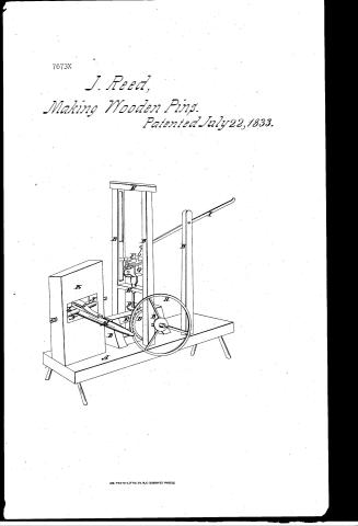
Jesse Reed's Patent Drawing for a Plug and Trunnel Geared Machine for Ship Building

National Archives, Restored Patent Drawings (Record Group 241) · Full-size scan at the National Archives · Catalog record
Show the text on the drawing Hide (96 words)
Words on the drawing as machine-read by the National Archives; not checked. Useful mainly for searching.
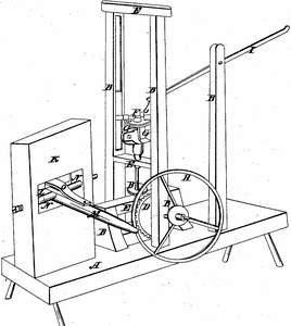
142. WOOD TURNING. / S. / Tubular Cutter Lathes. / $1- / CLASSIFICATION / 7673. X / DIVISION. / Jefse Reed's / Plug and Frunnel guard Machine / for Thip Building. / Patented July 22. 1833. / WI / OIR / References. / A. The Bench / H. The balance Wheel. / BBBBB. The Posts. / I. The Lever. / C, The Axle. / K The perpendicular Post. / DD. The bevel gear wheels / L. The Mortice. / EEE. The Crofo-bars. / M. The Lever / F. The Wheel. / NN. The Trunnions on Aale of the Lever. / G&. The circular Boxes. / 0. The Spring on Clearer.
USPTO scan
The patent as scanned by the USPTO
-
 Page 1
-
 Page 2
-
 Page 3
-
 Page 4
-
 Page 5


U.S. Patent and Trademark Office · Google Patents
Show the transcription Hide (1,401 words)
Machine transcription (LightOnOCR) of the pages as scanned by the USPTO, most of them the handwritten copies made when the records were restored after the 1836 fire. Not checked; it can misread handwriting, so compare it with the scan.
Page 1.
7673X
J. Reed,
Making Wooden Pins.
Patented July 22, 1833.
![Diagram of a machine for making wooden pins, labeled with letters A through H, showing a frame, a wheel, and various mechanical components.]
AM. PHOTO-LITHO. CO. N.Y. (OSBORNE'S PROCESS)
Page 2.
X7673
July 22, 1833
139.
Nephe Reed
Letters Patent
The schedule referred to in these Letters Patent and making part of the same containing a description in the words of the said Nephe Reed himself of his improvement called a plug & bevel gear machine for ship building. To all whom these presents shall come, be it known that I Nephe Reed of Marshfield in the County of Plymouth & commonwealth of Massachusetts have invented a plug & bevel gear machine for ship building, & the following is a full and exact description of the construction and operation of said machine as invented by me. In the first mode. The principle parts of said machine consist of a suitable bench or frame, posts, axles, spur wheels, balance wheel, crank screws & springs. The bench or frame is four feet in length one foot in width & about two feet in height. The height of the posts on which the axles are placed is about fourteen inches above the bench.
The diameter of the balance wheel is about twenty inches & weighs about forty pounds. The length of the springs or arms is sixteen inches. The length of the axle on which said springs or arms are placed is twelve inches, the diameter is one & a quarter inch made of round iron. The length of the other axle is about eighteen inches. On one end said axle is a crank on the other end is a spur wheel about twelve inches in diameter which drives a small wheel about four or six inches in diameter which is attached to the axle on which the balance wheel is placed. Attached to the end of said springs or arms are two circular boxes about three inches in length, the diameter of the inner circle of said boxes is an inch & a half at one end & about an inch from the other end is an inch & three
Page 3.
eighths of an inch to the end the diameter increases to two inches. Attached to one end of said boxes is a chisel or cutter one side of which is turned up like a gouge by which the tunnel is reduced from two inches to any size required. Said boxes being regulated by a screw that passes thru a clamp. A slide is placed on the upper side of said frame or bench & is made to slide in a direct line with the axle on which the cutter and balance wheel are placed. At one end of the slide is a perpendicular post having a hole thru the top, about two inches in diameter into which in the operation one end of the tunnel is put & is held fast by a lever or screw. This post may be made in two parts fastened together at the bottom & brought together with said lever by which means the tunnel is held. Two hands are necessary to put this machine in operation. In the second mode, said machine consists in a frame or bench axle & gear similar to the above described, near the centre of the frame are two perpendicular posts about four feet in height the space between them is about seven or eight inches. The upper part of said posts has a groove about three quarters of an inch square at the lower end of said groove is a cross bar & at the top there is another to keep them firm & steady. In said frame there are two other posts about eight or ten inches in height & about one foot distant from each other a cross bar is attached to the top of them. The main axle is about eighteen inches in length having a crank at one end and a balance wheel at the other about three feet in diameter & weighing from eighty to a hundred weight. This axle passes thru the first mentioned posts about six inches above the bench on said axle & just within the post near the balance wheel is placed a small gear wheel about eight or ten inches
Page 4.
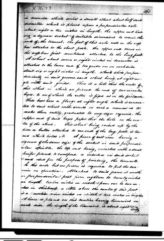
in diameter which drives a small wheel about half said diameter which is placed upon a perpendicular axle about eight or ten inches in length, the upper end having a square socket of suitable dimensions to receive the end of the tunnel, the foot of this axle rests in the cross bar attached to the short posts, the upper end turns in the cross bar first mentioned attached to the long posts. A wheel about seven or eight inches in diameter is attached to the lower end of two guides one on each side about six or eight inches in length, which slide perpendicularly in said grooves, said wheel being at right angle with said guides. There is a hole thru the centre of this wheel in which are placed the end of two circular boxes to one of which the cutter is fixed as in the first mode. These boxes have a flange at right angle which is connected to said wheel with screws in such a manner as to make them easily graduated to any size required. The upper end of said boxes passes thru the hole in the centre of the wheel. This wheel being raised up by the lever or button attached to one end of the long posts, is turned which holds it. A piece of cast iron having a square of the same size of the socket in said perpendicular can spindle, the top end being inverted with a small knife placed to correspond, is inserted in said socket and used for the purpose of pointing the tunnels. In this mode but one person is required to put the machine in operation. Attached to said frame is another perpendicular post from eighteen to twenty inches in length, twelve inches in width from one to two inches in thickness, a little above the centre of this post is a matine nine inches in width and two inches in height. A lever is placed on this matine having lammions on each side, the length of the lammions is about eight or half
Page 5.
half inches the end of them being counter sunk to receive the end of the screws on which the lever is hung, its length being about two & a half feet, the short end being about six inches from the pivots, & made to correspond with the shape of the plug required, the end of said lever being turned up, to keep the plug from slipping. On the front of said perpendicular post are elevations sufficient to affix two knives or chisels, two inches in width, having their inner edge half an inch the longest. These knives are placed on said elevations, the flat or straight sides inward, at the same distance & angles that the plug requires. On the top of said lever is a stout spring made fast. When the lever is raised one end of said spring hits upon a stop. The lever being further raised, it opens the spring sufficient to receive one end of the plug, then the lever is brought back & the plug is driven by the short end of the lever between the knives which takes off a shaven from each side, then being brought back by raising the lever it is turned over & the same operation repeated completes the plug.
Your petitioner claims the general construction of said machine above described & its application to the making of plugs & tunnels for ship building and others and rounds for ploughs excepting a tool now in use for rounding tunnels. I testimony that the above is a true specification of my said machine as above described. I do hereunto set my hand this tenth day of May Anno Domini 1833.
Witnesses
John Ford Jr
William Ford
[Signature]
[Seal]
[1136 with]
Published accounts: journal notice
Notice in the monthly list of patents, with remarks
Journal of the Franklin Institute, new ser., vol. 13 (1834), p. 30 · View the page
9. For a machine for Making Plugs and Trunnels for Ship Building; Jesse Reed, Marshfield, Plymouth county, Massachusetts, July 22.
Remarks. What are in the above title, called trunnels, are more properly treenails, which are the long wooden pins, generally of locust, used in ship building. The machine intended to be described is to be used for the rounding of these, and for the making of round plugs. The specification is not deficient in length, nor, apparently, in the attempt to afford a full description of the machinery, but we have rarely witnessed the bestowal of labour with less good effect. A drawing, with written references, does not suffice to amend the deficiences of the specification, and although we know something of machinery, and could construct one for making treenails and plugs, we should derive but little aid from the account of that before us, however much we might be inclined so to do. After this it will not be expected that we shall attempt to describe the thing; we however will give the claim. "Your petitioner claims the general construction of said machine above described, and its application to the making of plugs and trunnels for ship building, and rollers and rounds for ploughs; excepting a tool now in use for rounding trunnels." This exception is about as puzzling as the description itself.
DATAMP: illustration
Illustrations from DATAMP

DATAMP (Directory of American Tool and Machinery Patents), via the Internet Archive · Archived DATAMP page
About this record
- Patentee
- the Journal of the Franklin Institute, Journal
- Date
- the Name and Date index of patents, DATAMP, USPTO records
- Invention
- DATAMP
- Listed in
- the Name and Date index of patents, DATAMP, USPTO records, Jim Shaw's X-patent list, the Journal of the Franklin Institute, Burke's List of Patents (1847)
- The patentee's full name comes from the Franklin Institute's journal.
- The residence comes from the Franklin Institute's journal.
- Burke's 1847 Patent Office list gives the same patent.