

Drawings and documents
National Archives restored drawings: drawing
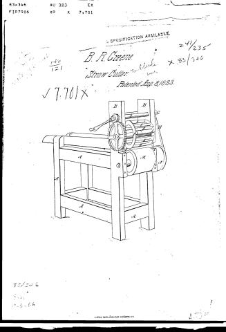
R. Greene's Patent Drawing for a Straw Cutter

National Archives, Restored Patent Drawings (Record Group 241) · Full-size scan at the National Archives · Catalog record
Show the text on the drawing Hide (41 words)
Words on the drawing as machine-read by the National Archives; not checked. Useful mainly for searching.
119. CARE OF LIVE STOCK. / 119. / Straw Cutters. / R.Green R. / 15 / Cutter and Bed. / [59 / Rotary Cylinder. / R.GREENE" / Straw-Culter. / CLASSINCATION / Patented Aug 8#1833. / 7701 - X / DIVISION. / Are
USPTO scan
The patent as scanned by the USPTO
-
 Page 1
-
 Page 2
-
 Page 3
-
 Page 4


U.S. Patent and Trademark Office · Google Patents
Show the transcription Hide (1,069 words)
Machine transcription (LightOnOCR) of the pages as scanned by the USPTO, most of them the handwritten copies made when the records were restored after the 1836 fire. Not checked; it can misread handwriting, so compare it with the scan.
Page 1.
83-346 …
Page 2.
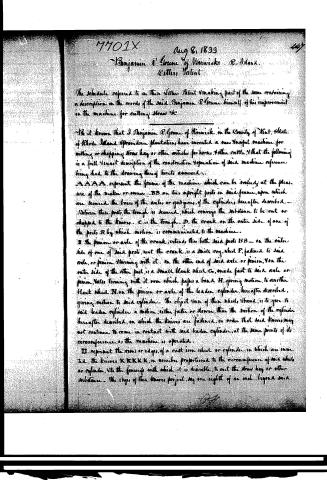
7701X Aug 8, 1833
Benjamin A. Groune of Warwick R. I.
Letters Patent
The schedule referred to in this Letters Patent making part of the same containing a description in the words of the said Benjamin A. Groune himself of his improvement in the machine for cutting straw etc.
Be it known that I Benjamin A. Groune of Warwick in the County of Kent, State of Rhode Island & Providence Plantations, have invented a new & useful machine for cutting or chopping straw hay or other articles for horses & other cattle & that the following is a full & exact description of the construction & operation of said machine reference being had to the drawing thereof hereto annexed.
AAAA represent the frame of the machine which can be varied at the pleasure of the maker or owner. BB are two upright posts in said frame, upon which are secured the braces of the axle or quidgans, of the cylinder, hereafter described. Between these posts, the trough is secured, which conveys the substance to be cut or chopped to the knives. C is the trough. D, the crank on the outer side of one of the posts B, by which motion is communicated to the machine.
B the pinion or axle of the crank, extends, thru both said posts BB — on the outer side of one of said posts, next the crank, is a small cog-wheel F, fastened to said axle, or pinion, turning with it. On the other end of said axle or pinion, is a small blank wheel G, made fast to said axle or pinion, also turning with it, over which passes a band H, giving motion, to another blank wheel N, on the pinion or axle of the leader cylinder, hereafter described, giving motion to said cylinder. The object of these wheels, bands, is to give to said leader cylinder a motion, either faster or slower, than the motion of the cylinder hereafter described, on which the knives are fastened, in order that said knives may not continue to come in contact with said leader cylinder, at the same points of its circumference, as the machine is operated.
II. represent the rims or edges, of a cast iron wheel or cylinder, in which are inserted the knives K K K K K, in number proportioned to the circumference of said wheel or cylinder, & to the fineness with which it is desirable to cut the straw hay or other substance. The edges of these knives project, say one eighth of an inch, beyond said
Page 3.
7701X
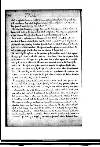
wheels or cylinders, varying in width to secure sufficient strength, according to the size of the machine. They extend lengthwise of said cylinder, or from wheel to wheel, and are held firm at each end, by clay bolts, or otherwise.
The sides of the knives are in right lines from the circumference of said wheels or cylinders to the center of the axle of said wheels or cylinders. These edges are ground with a bevel towards the side, where they first meet the substance to be cut.
These wheels or cylinders move between said posts BB, the axle, passing through boxes attached to them—outside the post near the crank on said axle, is a cog wheel, to playing into and receiving its motion from the small cog wheel B attached to the axle of the crank, as before described. M represents another cylinder, covered with lead, the axle of which passes through the slide boxes CC, attached to the posts BB.
The surface of this cylinder, in the operation of the machine, must be kept against the edges of the knives, in the other cylinder. It is drawn and held in its proper position by the screws SS. The upper ends of these screws turn in shear against the boxes of the axle of the wheels, or cylinders II. The lower ends screw into nuts, in the boxes of the cylinder M. The object of these screws is to draw the two cylinders together when their surfaces are worn away, by the operation of the machine. Their diameters diminished. The straw, hay, or other substance, to be cut, passes between these cylinders. In its passage, it is cut into pieces of the length of the distance between the knives. The knives are taken out when they are to be ground.
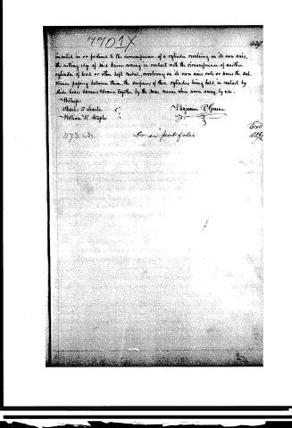
The advantages of this machine, over machines made for the same purpose, are the ease with which it is operated, the facility with which any quantity of hay, or straw may be cut. The length of time, it may be used, without needing to be ground or sharpened, the edges of the knives, never coming in contact with one another, but only with a soft metal and the substance to be cut, but more than all, in the fact that in case a stone or other hard substance, concealed in the substance to be cut, is brought in contact with the knives it will injure only a small part of the machine and the owner by inserting a new knife in place of the one injured is delayed in this operation but a very short time, or he can continue his operation without that, the effect of that injury being only to let the substance to be cut, pass the injured knife without being severed. What I claim as new is, my own invention in the above described machine. For the use of which I ask an exclusive privilege in the construction of machine for cutting or chopping straw or hay for cattle throats, having the knives.
Page 4.
17701X
429
inserted in or fastened to the circumference of a cylinder revolving on its own axis, the cutting edge of said knives coming in contact with the circumference of another cylinder of lead or other soft metal, revolving on its own axis, cuts or grinds the substance passing between them, the surfaces of these cylinders being held in contact by side boxes, screws, drawn together by the same means, when worn away by use.
Witnesses:
Charles T. Seaton
William R. Staples
Benjamin P. Greene
1173 w3
for an "portfolio"
Expo
1170
Published accounts: journal notice
Notice in the monthly list of patents, with remarks
Journal of the Franklin Institute, new ser., vol. 13 (1834), p. 112 · View the page
7. For a Straw Cutter; Benjamin R. Green, Warwick, Kent county, Rhode Island, August 8.
Remarks. The claim made by the patentee will afford a tolerably correct idea of the mode in which this straw cutter acts; it is in the following words:" What I claim as new, and as my own invention in the above described machine, and for the use of which I ask an exclusive privilege, is the construction of a machine for cutting or chopping straw, or hay, for cattle and horses, having knives, inserted in, or fastened to, the circumference of a cylinder revolving on its own axis; the cutting edges of said knives coming in contact with the circumference of another cylinder, of lead, or other soft metal, revolving on its own axis, cuts or severs the substance passing between them; the surfaces of these cylinders being held in contact by slide boxes and screws, and drawn together by the same means, when worn away by use." The cutting cylinder, with its knives, is placed above a cylinder covered with lead, and the straw is fed between them by means of a trough. The cutting cylinder has rims projecting out at each end to receive the knives which extend from one to the other. The number of knives must be governed by the size of the machine, as must also the velocity of the motion. The cylinder covered with lead may be moved with the same, or with greater or less velocity, than that of the cutting cylinder, the main object of its motion being constantly to vary the part upon which the knives shall act. The specification is clearly drawn up, and we think conforms in all respects with the requirements of the law.
About this record
- Patentee
- DATAMP
- Date
- the Name and Date index of patents, DATAMP, USPTO records
- Invention
- DATAMP
- Listed in
- the Name and Date index of patents, DATAMP, USPTO records, Jim Shaw's X-patent list, the Journal of the Franklin Institute, Burke's List of Patents (1847)
- The Franklin Institute's journal spells the name differently.
- Burke's 1847 Patent Office list gives the same patent.