

Drawings and documents
USPTO scan
The patent as scanned by the USPTO
-
 Page 1
-
 Page 2
-
 Page 3
-
 Page 4
-
 Page 5
-
 Page 6
-
 Page 7


U.S. Patent and Trademark Office · Google Patents
Show the transcription Hide (2,201 words)
Machine transcription (LightOnOCR) of the pages as scanned by the USPTO, most of them the handwritten copies made when the records were restored after the 1836 fire. Not checked; it can misread handwriting, so compare it with the scan.
Page 1.
J. M. McGregor, Jr.,
Planing Machine,
7730X
Patented Aug. 28, 1833.
Page 2.
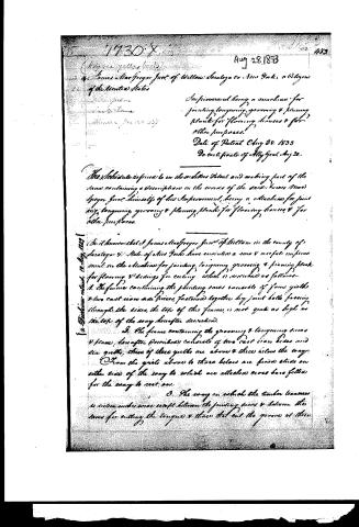
Aug 28, 1833
Improvement being a machine for jointing, tonguing, grooving & planing planks for flooring houses & for other purposes.
Date of Patent Aug 28, 1833
Do certificate of Ally Gent. Aug 28.
The Schedule referred to in the aforesaid Patent and making part of the same, containing a description in the words of the said James MacGregor Junr. himself of his Improvement, being a machine for jointing, tonguing, grooving & planing planks for flooring houses & for other purposes.
It is known that J. James MacGregor Junr. of William in the county of Saratoga & State of New York have invented a new & useful improvement in the machine for jointing, tonguing, grooving & planing planks for flooring & ceilings for ceilings which is described as follows—
1. The frame containing the planing saws consists of four girdles & two cast iron side pieces, fastened together by joint bolts passing through the sides, the top of this frame is not quite as high as the top of the way hereafter described.
2. The frame containing the grooving & tonguing saws & plane (hereafter described) consists of two cast iron sides and six girdles, three of these girdles are above & three below the way. From the girdles above to those below are fixed sticks on either side of the way to which are attached cross bars fitted for the way to rest on.
3. The way on which the timber traverses is set so under saws except between the jointing saws & between the saws for cutting the tongue & those that cut the grooves at their
Page 3.
484. 77307
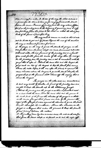
places it is only four inches. In the top of this way, the wheel contains a groove for the chains to turn in for carrying forward the plank between the saws. Towards the front of the jointing saws the way extends fifteen feet from the jointing saws to the tonguing & grooving saws, it is fifteen feet long from this place to the wheel on which the chain goes back of the frame, it is seven feet long.
This way must be secured on rests, so that it does not be liable to get out of place. (Beyond the size of the machine the way is continued fourteen feet more).
4. The grooves on the way to guide the plank, the grooves on the side furthest from the plane shaft are made permanent & parallel with each other, the one forward of the jointing saw is a fourth of an inch further from the centre of the way than the one of the jointing saw, the jointing saw is set to correspond with the gauge that is after it. Behind the saws that cut the tongue the gauge rests on top of the tongue to keep the plank from rising between the rollers before, & the one after the plane, & against the main shoulder above the tongue, to guide the plank straight, this gauge is sharp at the forward end & shaves off the edge that is above the tongue.
The grooves on the other side are movable so as to suit any width of plank. In front of the jointing saw is a tongue to keep the plank up to the stationary gauge.
Behind the jointing saw the gauge is as thin as possible & even in a line with the saw. From the saws that cut the groove to the back part of the frame the shoulder of the gauge is as thick as the under flange that forms one side of the groove, the edge of this flange presses against the shoulder to guide the plank straight through the machine. Above this shoulder on the gauge is a tongue that enters the groove to keep the plank from rising between the rollers.
5. The jointing done by two circular saws, the one on the side furthest from the plane shaft is so placed as to cut the edge off
Page 4.
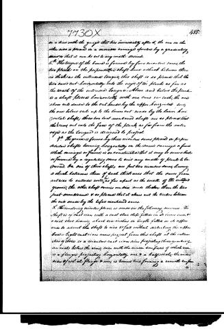
in a line with the guard that lies immediately after it, the one on the other side is placed in a movable carriage operated by a graduating screw so that it can be set to any width desired.
6. The tongue of the board is formed by four eccentric saws, the two placed on the perpendicular shaft have a shank between them as thick as the intended tongue, this shaft is so placed that the two saws cut horizontally into the edge of the plank as far as the width of the intended tongue. Above and below the plank is a shaft placed horizontally with one saw in each, the one above cuts down to the cut made by the upper horizontal saw, the one below cuts up to the lower cut made by the lower horizontal shaft; these two last mentioned shafts are so placed that the saws cut into the face of the plank, as far from the outer edge as the tongue is designed to project.
7. The groove is formed by three eccentric saws placed on three vertical shafts turning horizontally in the same carriage or frame which carriage or frame is so constituted that it may be moved back or forward by a regulating screw to suit any width of plank to be made. On one of these shafts are put two eccentric saws, having a shank between them of such thickness that the saws from outside to outside will be as far apart as the width of the intended groove, the other shaft carries one saw made thicker than the two just mentioned & so placed that it clears out the timber between the cuts made by the before mentioned saws.
8. The revolving eccentric plane is made in the following manner. The shaft is of cast iron with a cast steel step fitted in its lower end & a cast steel bearing about six inches in length fitted in its upper end to admit the shaft to rise & fall without disturbing the upper bed. Eight cast iron arms project from this shaft at the extremities of there is a circular cast iron rim projecting three quarters of an inch below the arms, even with the inner surface of which rim is a flange projecting horizontally one & a half inch; the inner rim of which flange & rim is turned true forming a smooth surface.
Page 5.
to pass freely over the plank to be planed. In this flange are certain slots forming throats to admit the inner edges of the plank now, at the back part of which slots are projections extending from the back of the rim as far as the outer edge of the flange to which they are cast solid having the same inclination as the rim, their projections from the back part of the slots as near as the back pieces on which the plank rims rest, & are fastened by screws bolts & nuts. Each plane rim is from inches long & two inches wide, rounded on the outer corners the front edge passing through the throat being nearly square, this edge the outer corner & up the outer edge as far as the plank should be over the desired thickness is made sharp.
To support this revolving plane, a bar extends from one girt to another directly under the centre of the shaft below the way. On this bar is fastened a box to receive the step placed at the lower end of the revolving plane shaft. A plate forming the stationary part of this box is twelve inches long, four inches wide with a rise in the centre four inches high & four inches in diameter, thus the centre of which is drilled an aperture two inches in diameter in a line with the centre of the shaft in this aperture is fitted a piece of metal having a cavity in its upper end to admit the point of the shaft & is made to rise & fall by a regulating screw to elevate or depress the plane at pleasure; the side of the rise is tipped & a screw fitted in so as to press against the side of the rise to keep it stationary when required.
4. The feeding is performed by an endless chain passing over two wheels one at the end of the frame in which the revolving plane is placed & the other at the first end of the way, the first mentioned wheel has cogs on its periphery working in the links of the chain. On this chain are fastened hooks which by hold of the end of the plane on the chain carrying it forward to the cause & plane. 10. Bolts for holding down the plank, there are three of these.
Page 6.
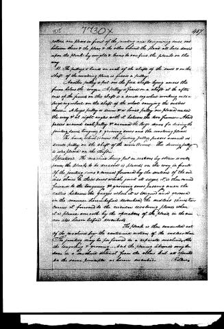
rollers, one placed in front of the jointing and tongueing saws, one between these & the plane, & the other behind the plane all here drawn upon the plank by weights & levers to confine the plank on the way.
11. The pulleys & bands on each of the shafts of the saws & on the shaft of the revolving plane is fixed a pulley. Another pulley is put on the feed shaft by going across the frame below the ways. A pulley is fixed on a shaft at the other end of the frame; on this shaft is a small cogwheel working into a large cogwheel on the shaft of the wheel carrying the endless chain. A large pulley or drum & a loose pulley are placed under the way & at right angles with it between the two frames. Band passes around each pulley & around the large drum for driving the jointing saws, tongueing & grooving saws and the revolving planes. The band wheel drives the feeding pulleys passes around a small pulley on the shaft of the main drum. The driving pulley is also placed on the shaft.
Operations: The machine being put in motion by steam or water power, the plank to be dressed is placed on the way in front. If the jointing saws & carried forward by the motion of the endless chain to those saws which joint its edges, it is then carried forward to the tongueing & grooving saws passing under the rollers between the gauges where it is tongued and grooved in the manner hereinbefore described; the endless chain then carries it forward to the circular revolving planes where it is planed smooth by the operation of the plane, in the manner also hereinbefore described.
The plank is then conducted out of the machine by the continuous motion of the endless chain. The jointing may be performed in a separate machine, like the tongueing & grooving. And the planing thereof may be done in a machine distinct from the others but all operated on the same principles as herein described.
Robins
Page 7.
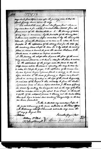
may also be fixed before & after the jointing saw, to keep the plank firmly down upon the way.
I do what I the said James MacGregor just claim as my invention & for which I do bear Letters Patent from the Government of the United States is: 1. The planning of boards of any size or dimension by the principle of the turning tool & plane now united as before described, or by the turning tool separate from the plane now or so near as to retain the same principle. 2. The application of the sliding board for the stop of the revolving plane shaft to turn in & by which the revolving plane is raised & lowered to give the desired thickness to the planks made & applied as before described. 3. The passing the shaft thru beyond the face of the revolving circular plane so as to have a stop for the plane to rest on. 4. The application of the guage under the plane to keep the stuff down while the plane is operating, this may be done by a roller, but I prefer the guage. 5. The application of the common circular saw to joint tongue & groove plank or siding in the manner before described. 6. The mode of forming a tongue on a board plank or siding by cutting in the edge of the plank horizontally on each side of the tongue & then vertically to form the shoulder by circular saw as herein before described. 7. The mode of forming the groove by making two horizontal cuts in the edge of the plank with two circular saws as far apart & as deep as the width & depth of the intended groove & clearing out the timber between these cuts by a circular saw revolving horizontally in the manner herein described.
Further to illustrate my invention I refer to the model & drawing of the same deposited in the Patent Office.
In Testimony whereof I hereunto subscribe my name this 19th day of August 1833
James MacGregor Jr.
Witnesses
William P. Elliot
P. S. Laughlin
(Seal perfect)
Published accounts: journal notice
Notice in the monthly list of patents, with remarks
Journal of the Franklin Institute, new ser., vol. 13 (1834), p. 120 · View the page
26. For a Machine for Planeing, Tongueing and Grooving Boards; James Mac Gregor, jr., Wilton, Saratoga county, New York, August 28.
Remarks. The planeing part of this machine operates in the same way with the well known English planeing machine invented many years since by Mr. Brama. That is, a wheel fixed to a vertical shaft is made to revolve horizontally, the lower side of this wheel forming the face of the plane. The latter part, the patentee says, is to be made of cast iron, and turned true. In it there are to be sixteen slots, which are to receive the plane irons, and to form the throats of the planes; the irons are to be fixed in their places by means of screws. The edges of the plane irons are to be turned up so as to cause them to operate, in that part, like a turning gouge, whilst the middle part is straight. The board to be planed must, of course, pass on one side of the vertical shaft, and is traversed by the planes. The ends of the shaft work in boxes which can be raised and lowered to adapt the planes to the thickness of the stuff to be planed. The board is to be carried forward by an endless chain furnished with hooks for that purpose, whilst it rests on ways extending in both directions from the planeing wheel. The jointing is performed by two circular saws, one of which is on an adjustable frame, to adapt it to the desired width of the stuff. This jointing is the first operation effected by the machine, and to this succeeds the tongueing and grooving, which, also, is done by circular saws. For tongueing there are two circular saws on a horizontal shaft, standing at such distance apart as is required for the thickness of the tongue, and two other saws, which are placed with their shafts at right angles to these, one of them to cut above and the other below the board, into the kerfs formed on the edge, and thus to complete the tongue. The grooving is performed by three circular saws, two of which cut the width of the groove, being fixed on the same shaft, like the first two for tongueing; the third, which is on a separate shaft, must be thick enough to take out the middle piece left by the other two. From the grooving saws the board passes under the planes, where it is finished. We cannot follow the description through all its details, and must omit some which are referred to in the claims. The mode of planeing by a horizontal wheel, and some other things which have been previously done in a similar way, such, for example, as keeping the board down by rollers and weights, are not claimed; those which are so, being "the planeing of timber of any size or dimensions by the principle of the turning tool and plane iron united, as described; or the turning tool separate from the plane iron, or so near as to retain the same principle. The application of the sliding box for the step of the revolving plane shaft to turn in, and by which the revolving plane is raised and lowered to give the desired thickness to the plank. The making the shaft through beyond the face of the revolving circular plane, so as to have a step for the plane to rest on. -The application of the gauge under the plane to keep the shaft down while the plane is operating. The application of the common circular saws to joint, tongue and groove plank, in the manner before described. The mode of forming a tongue on a board, by cutting in the edge of the plank horizontally, on each side of the tongue, and then vertically, to form the shoulders by circular saws. The mode of forming the groove by making two horizontal cuts in the edge of the plank with two circular saws, and cleaning out the timber between these cuts by a circular saw." The jointing by circular saws has been frequently done, and we do not perceive any essential difference in the mode proposed from that which has been previously adopted. In Woodworth's planeing machine, the grooving is effected by a single circular cutter, operating very much like the third circular saw in the present case; to us the principle appears to be the same, and the three saws no improvement.
DATAMP: illustration
Illustrations from DATAMP
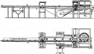
DATAMP (Directory of American Tool and Machinery Patents), via the Internet Archive · Archived DATAMP page
About this record
- Patentee
- DATAMP
- Date
- the Name and Date index of patents, DATAMP, USPTO records
- Invention
- DATAMP
- Listed in
- the Name and Date index of patents, DATAMP, USPTO records, Jim Shaw's X-patent list, the Journal of the Franklin Institute, Burke's List of Patents (1847)
- Burke's 1847 Patent Office list gives the same patent.