

Drawings and documents
USPTO scan
The patent as scanned by the USPTO
-
 Page 1
-
 Page 2
-
 Page 3


U.S. Patent and Trademark Office · Google Patents
Show the transcription Hide (833 words)
Machine transcription (LightOnOCR) of the pages as scanned by the USPTO, most of them the handwritten copies made when the records were restored after the 1836 fire. Not checked; it can misread handwriting, so compare it with the scan.
Page 1.
7756X
W. Field,
Olirer
Patented Sept. 14, 1833.
Page 2.
Sept. 24, 1833
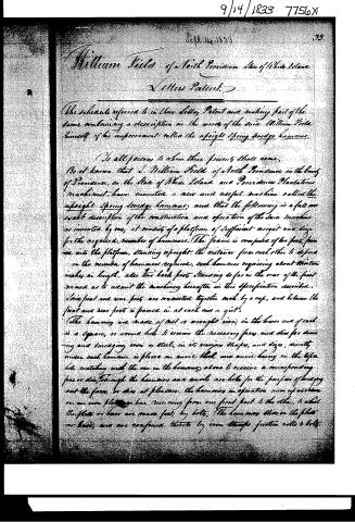
William Field of North Providence, State of Rhode Island.
Letters Patent.
The schedule referred to in these Letters Patent and making part of the same containing a description in the words of the said William Field himself of his improvement called the upright spring stodge hammer.
To all persons to whom these presents shall come,
Be it known that I, William Field of North Providence in the County of Providence, in the State of Rhode Island and Providence Plantations, machinist, have invented a new and useful machine called the upright spring stodge hammer, and that the following is a full and exact description of the construction and operation of the said machine as invented by me, it consists of a platform of sufficient weight and size for the required number of hammers. The frame is composed of two front posts into the platform, standing upright, the distance from each other to depend on the number of hammers required, each hammer requiring about thirteen inches in length, also two back posts standing so far in the rear of the first named as to admit the machinery hereafter in this specification described. The front and rear posts are connected together each by a cap, and between the front and rear posts is framed in at each end a girt.
The hammers are made of cast or wrought iron, in the lower end of each is a square, or round hole to receive the necessary faces and dies for drawing and smelting iron or steel, in its various shapes and sizes, directly under each hammer is placed an anvil block and anvil having on the opposite side matching with the one in the hammer above to receive a corresponding face or die. Through the hammers and anvil are holes for the purpose of carrying out the faces, or dies at pleasure. The hammers in operation move up and down on an iron platform bar running from one front post to the other, to which the plates or bars are made fast by bolts. The hammer slides on the platform bar, and are confined thereto by iron straps, friction rolls & bolts.
Page 3.
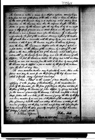
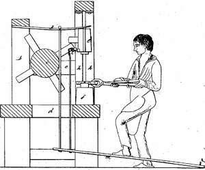
The hammer in motion is raised by a shaft or cylinder running horizontally from one end of the frame to the other or lever or levers, on the pivot in the rear of the hammer having on its surface any which striking similar projections on the hammer raises than the required height. The blow or stroke is given by the hammer after the any being it by its own weight, since a stiff spring of good iron or steel placed on the upper end of the hammer, and is forced down upon the hammer by a lever, which is operated by the foot of the workman standing in front of the machine. The aforesaid lever is connected with the spring by an iron rod, and the workman is able to give the hammer any force he chooses, by forcing down the lever. The hammer is stopped when the shaft or cylinder is in full motion, at the pleasure of the workman, by a spring & catch placed on the main plate by the side of the hammer, which catch is forced into a notch on the hammer by said spring, and lets the hammer up while stopped. To put the hammer in motion the spring and catch are drawn back by an iron rod running from the catch to the lever, by means of which the hammer may be stopped or put in motion by the foot of the workman upon the lever at any time.
The above described machine may be operated by water, steam or horse power, and may be used for all the purposes of the trip hammer over which it possesses many important advantages.
I claim a Patent as the inventor of said machine, and for applying it to the purposes of blacksmithing, for the construction and form of the hammer, for the frame of putting in the face and dies, for the plan of holding the hammer up when stopped by spring and catch, for the manner of connecting the hammer to the main iron plate or bar by straps, friction rolls and bolts, for the manner of giving the blow by the spring and lever, connected by an iron rod at the pleasure of the workman, for the plan of drawing back the catch and letting the hammer in motion, for the manner of unlocking out the face, and dies and for being able to put from four to six hammers into the space generally occupied by one trip hammer.
Wm. H. W. H.
Thomas Jefferson
William H. H.
Filed 20th 1840
Published accounts: journal notice
Notice in the monthly list of patents, with remarks
Journal of the Franklin Institute, new ser., vol. 13 (1834), p. 177 · View the page
19. For Printing Books, &c. by improved machinery; Harvey Betts, Norwalk, Fairfield county, Connecticut, September 14.
Remarks. We are informed by the patentee that the general principle of his invention, is the printing of paper in a continuous sheet, on both sides, either directly from the machine on which the paper is made, or from a reel, or roller, upon which it is wound. We know that the printing press has been actually appended to the cylinder paper mill, by a gentleman in this country, so as to print the sheet as it is made; and we also know that it has been frequently proposed to do so by others; but we are unable to perceive any advantages from such a procedure which would not be more than counterbalanced by its unavoidable inconveniences. Paper has been printed from a sheet of many hundred yards in length, on one side, but we doubt whether this has been advantageously done, on both sides, although it has been attempted, on a cylinder machine. It would be no easy thing in this process to make good register for book work, although it might answer in the newspaper press. Should the present patentee have accomplished this, he will certainly have made another great step in the typographical art. It appears, however, that he has followed the usual, and almost unavoidable course of inventors, in patenting his machine before it has been essayed with that care which is necessary to the establishment of its character. The inventor says, that with the imperfect press by means of which he has experimented, he has seen a length of paper printed in ten seconds, sufficient to make eleven sheets of medium, with paper of only two VOL. XIII.-No. S.-MARCH, 1834. 23 feet in width, whilst he has it in contemplation to extend this width to ten, or even twenty feet. We have no reason to doubt the goodness of his judgment as a printer, but we cannot say so much of him as a practical mechanist. A cylinder paper machine, and a roller printing press, twenty feet wide, would, we think, appal the great mechanician of Syracuse, had his life been prolonged in vigour to the present day, and his mind imbued with a knowledge of all the wonders which have been effected in the mechanic arts. We like enthusiasm, however, as without it men will almost invariably fall short of what it is in their power to accomplish. The description given of this apparatus, and the drawing which accompanies it, are both of them crude, being defective in those details which would enable any person to carry the plan into effect; this, we apprehend, has arisen from causes to which we have already made some allusion. Three different processes, and modifications of the machinery, are spoken of as being contemplated by the patentee; he has not, however, made claim to either of them, and the entire novelty of each, in all its parts, may certainly admit of doubt. It is said that this machine differs from the Napier press in the employing of the whole surface of the cylinder, instead of allowing its intermitted action during the process of inking. In the first method proposed, stereotype plates are alone to be employed; these are to be firmly attached to a set of blocks, not fewer than six, of the width of a page, and in length equal to that of the paper, "which may be indefinite." The blocks are to be hinged together on their edges, so as to form an endless chain. They are to be carried over a polygonal roller of wood, strong enough to sustain the pressure of the cylinder, by which the impression is made. In the second process, either stereotype plates or movable types are to be employed upon similar blocks, united by strips of iron in such a way as never to be inverted, so as to allow of the falling out of the types, In the first process, the inking is to be effected below, in the second above, the types, or blocks. A third method noticed, is the employment of two or more movable forms, passing over a roller, and under a cylinder; the forms after receiving the impression are to descend under the roller, and thence be returned to the position in which they are to receive a new impression. The modes of inking may be various, but that preferred is by the employment of an endless apron of leather, as wide as the form, and revolving round two rollers about nine inches apart. This is to receive the ink from one roller, and to communicate to another, whence it is to be transferred to the form.
Published accounts: journal notice
Notice in the monthly list of patents, with remarks
Journal of the Franklin Institute, new ser., vol. 13 (1834), p. 178 · View the page
We have thus given an extended account of this patent; and if it be not a clear one its deficiency in this respect does not rest with us, as we have carefully examined the specification and drawing, which ought, in conjunction, to make the plans fully known. We have not resorted to the model, which is referred to in the specification; the reason for omitting this, has been assigned on more than one previous occasion. 20. For a Swage Hammer, called the Upright Spring Swage Hammer; William Field, North Providence, Providence county, Rhode Island, September 14.
Remarks. What is here called a swage hammer, consists of a vertical slide of iron, confined by a suitable frame, or socket, and having, at its lower end, a perforation to receive a die, or swage. Immediately below this is an anvil, which is also furnished with an opening to receive a face, or swage, and a hole to wedge it out when it requires to be removed. Of these hammers and anvils any convenient number may be placed in a line, and a revolving shaft furnished with cams, or lifters, raises the hammers, or slides, and allows them to fall upon the work. To increase the force of the blow, springs are made to bear upon the upper ends of the hammers, and by means of a lever, or treadle, the pressure of these springs may be increased at pleasure. Each hammer is furnished with a catch by which it may be held up when it is to be put out of action. The patentee claims a patent for "the invention of said machine, and for applying it to the purpose of blacksmithing; for the construction and form of the hammers; for the plan of putting in the faces and dies; for the plan of holding the hammer up when stopped, by a spring and catch; for the manner of connecting the hammers to the main iron plate, or bars, by straps, friction rolls, and bolts; for the manner of giving the blow by the spring and lever connected by an iron rod, at the pleasure of the workman; for the manner of drawing back the catch and setting the hammer in motion; for the manner of wedging out the faces and dies, and for being able to put from four to six hammers into the space generally occupied by one trip hammer." Perhaps a claim to the particular arrangement of the foregoing machinery, might have been sustained; but in descending to all the particular parts, some of which are probably as old as the time of Vulcan, we are convinced that there are things claimed which are no more patentable than would be the unlocking of the shop door, and the lighting of the forge fire.
DATAMP: illustration
Illustrations from DATAMP
DATAMP (Directory of American Tool and Machinery Patents), via the Internet Archive · Archived DATAMP page
About this record
- Patentee
- DATAMP
- Date
- the Name and Date index of patents, DATAMP, USPTO records
- Invention
- DATAMP
- Listed in
- the Name and Date index of patents, DATAMP, USPTO records, Jim Shaw's X-patent list, the Journal of the Franklin Institute, Burke's List of Patents (1847)
- Burke's 1847 Patent Office list gives the same patent.