

Drawings and documents
USPTO scan
The patent as scanned by the USPTO
-
 Page 1
-
 Page 2
-
 Page 3
-
 Page 4


U.S. Patent and Trademark Office · Google Patents
Show the transcription Hide (1,084 words)
Machine transcription (LightOnOCR) of the pages as scanned by the USPTO, most of them the handwritten copies made when the records were restored after the 1836 fire. Not checked; it can misread handwriting, so compare it with the scan.
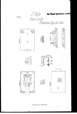
Page 1.
7758X
J. Kyle,
Door Lock,
Patented Sep. 16, 1833.
No Printed Specification Available
Fig. 2
Fig. 3
Fig. 4
Fig. 5
Fig. 6
Fig. 7
Fig. 8
Fig. 9
Fig. 10
Fig. 11
Fig. 12
Fig. 13
Fig. 14
Fig. 15
Fig. 16
Fig. 17
Fig. 18
Fig. 19
Fig. 20
Fig. 21
Fig. 22
Fig. 23
Fig. 24
Fig. 25
Fig. 26
Fig. 27
Fig. 28
Fig. 29
Fig. 30
Fig. 31
Fig. 32
Fig. 33
Fig. 34
Fig. 35
Fig. 36
Fig. 37
Fig. 38
Fig. 39
Fig. 40
Fig. 41
Fig. 42
Fig. 43
Fig. 44
Fig. 45
Fig. 46
Fig. 47
Fig. 48
Fig. 49
Fig. 50
Fig. 51
Fig. 52
Fig. 53
Fig. 54
Fig. 55
Fig. 56
Fig. 57
Fig. 58
Fig. 59
Fig. 60
Fig. 61
Fig. 62
Fig. 63
Fig. 64
Fig. 65
Fig. 66
Fig. 67
Fig. 68
Fig. 69
Fig. 70
Fig. 71
Fig. 72
Fig. 73
Fig. 74
Fig. 75
Fig. 76
Fig. 77
Fig. 78
Fig. 79
Fig. 80
Fig. 81
Fig. 82
Fig. 83
Fig. 84
Fig. 85
Fig. 86
Fig. 87
Fig. 88
Fig. 89
Fig. 90
Fig. 91
Fig. 92
Fig. 93
Fig. 94
Fig. 95
Fig. 96
Fig. 97
Fig. 98
Fig. 99
Fig. 100
AM. PHOTO-LITHO. CO. N.Y. (OSBORNE'S PROCESS.)
Page 2.
Sept 16 1838
Samuel Ryle, Raufos, County of Rockland, New York
7758X Sellers Patent
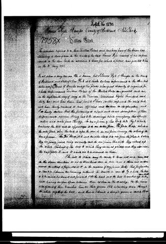
The debatable referred to in their Sellers Patent and making part of the same, can claiming a description in the words of the said Samuel Ryle himself of his improvements in the door lock in addition to those for which a patent was granted him on the 11th May 1832.
To all whom it may concern: Be it known that Samuel Ryle of Raufos in the County of Rockland and State of New York did make certain improvements in the door lock intended for doors of banks and in the places where great security is required for which improvements Sellers Patent of the United States was granted unto me on the eighteenth day of May in the Year one thousand eight hundred and thirty two; and that since that period I have further improved the said lock and have thereby rendered it more efficient and secure in its operation and I do hereby declare that the following is a full and exact description of these improvements reference being had to the drawings which accompany this specification and make part thereof. The box or frame of this Lock A A Fig 1 which contains the bolt and its appendages is of one entire piece. The Plate B also which is the outer plate when the lock is upon the door is of one piece covering the whole of the box or frame. The Two Strips C C and the other Strips D D rise from the plate A which they are firmly joined being essentially one piece therewith they extend up the whole thickness of the bolt B which they serve as guides and they also serve the Cupplate C and D which are to be screwed on there.
The bolt B which may be made to throw out one or more arms in the same direction or as is sometimes done in new locks to throw out in two several directions is perforated at E in the manner of my former locks; this perforation is marked in likeness containing within it the handle or arm O by which the bolt is to be moved backward and forward. At the back end the bolt is divided off into two parts leaving an open space between them as seen in the drawing. In the inner side of each of these branches there are three grooves 1 1 1 extending down through the whole depth of the bolt; and there is likewise a single groove or notch 2 2 or
Page 3.
The outer ends of each of these three members extend only through the thickness of a flange which projects over one side of the body, along each of these edges to a distance equal to the depth of the groove in which, and which may be one fourth of an inch more or less in thickness. The use of these flanges will be presently described. The ends of the lower piece by me in my said or said patent, which I have deemed to hold the bolt until they were lifted by the key, are merely in any other manner of lifting pieces usually made of steel plates in the general form of that shown at X in the place as at X by Y. These pieces in their various capacities determine the use of the lock.
These four projecting ends, when they are placed between the guide sheets DD are guided by three small feet or one row by the two rows of the grooves EE according to circumstances. The open space between or beneath the foot of the key is upon which the cases or latches are placed in a way much like that described in my first patent. However, usually make the opening in these cases or latches open or in any other form by which they will be held in proper directions when slipped upon the stem or shaft of the key.
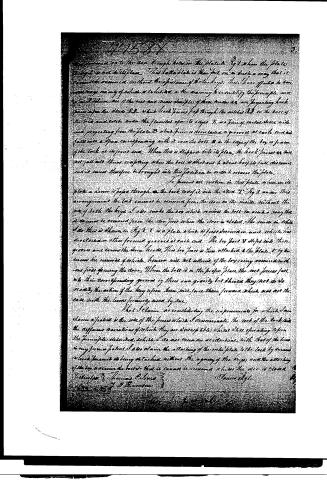
These are shown separately at N N and the nearly where they are fixed at O. The shape of the opening to may be varied in any way so that it admits the key to act properly upon the lock pieces. These pieces when they have but one projection or more than two projections at each end the bolt being carried accordingly to receive these. I generally make the cases or latches N of different lengths and also of different thicknesses and form a lock from a corresponding each case or latch, following the corresponding pieces in order that they may be readily placed so as to harmonize in the combination. The number of projections of which these pieces are provided may or within of them may be indefinitely extended. Fig 5 is a transverse section of the bolt through the grooves in which the lock pieces pass, and also through the pieces themselves. This section shows also the flanges formerly named projecting from the two sides N N of the bolt. These with a shape passing through the two holes O may be used to move the bolt, but for the purpose to which it is intended, most commonly to apply this lock I employ only a short piece P here projecting through the plate of the lock which is attached to the door Fig 6. The kind of key which may be used to act upon the tumblers and move the bolt with the same which may be given to the piece which is to pass over the stone P are shown in Fig 6. This lock is
Published accounts: journal notice
Notice in the monthly list of patents, with remarks
Journal of the Franklin Institute, new ser., vol. 13 (1834), p. 181 · View the page
26. For an improvement on the Door Lock, for which the preceding patent was obtained; James Kyle, Ramapo, Rockland county, New York, September 16.
Remarks. We mentioned the lock upon which this is an improvement, in very favourable terms, and those alterations which experience has suggested in it, have certainly rendered it much more perfect. For the lever latches, working upon a fulcrum, and raised by the key, of which we spoke particularly, there have been substituted plates of metal, which slide up and down, and in so doing are acted upon by the cams on the key, without its being necessary to depend upon their own gravity in resuming their places. We have examined one of the locks, which is placed upon a bank door, and have seen few, if any, which are equally simple and secure. As we formerly observed, a drawing would be required to render its construction intelligible.
About this record
- Patentee
- DATAMP
- Date
- the Name and Date index of patents, DATAMP, USPTO records
- Invention
- DATAMP
- Listed in
- the Name and Date index of patents, DATAMP, USPTO records, Jim Shaw's X-patent list, the Journal of the Franklin Institute, Burke's List of Patents (1847)
- Burke's 1847 Patent Office list gives the same patent.