

Drawings and documents
USPTO scan
The patent as scanned by the USPTO
-
 Page 1
-
 Page 2
-
 Page 3
-
 Page 4
-
 Page 5
-
 Page 6
-
 Page 7
-
 Page 8
-
 Page 9
-
 Page 10
-
 Page 11
-
 Page 12


U.S. Patent and Trademark Office · Google Patents
Show the transcription Hide (4,237 words)
Machine transcription (LightOnOCR) of the pages as scanned by the USPTO, most of them the handwritten copies made when the records were restored after the 1836 fire. Not checked; it can misread handwriting, so compare it with the scan.
Page 1.
7760Y
W. B. Leonard.
Drawing Frame for Spinning Mach.
Patented Sept. 16, 1833.
2 Sheets—Sheet 1

Page 2.
7760X
W.B. Leonard.
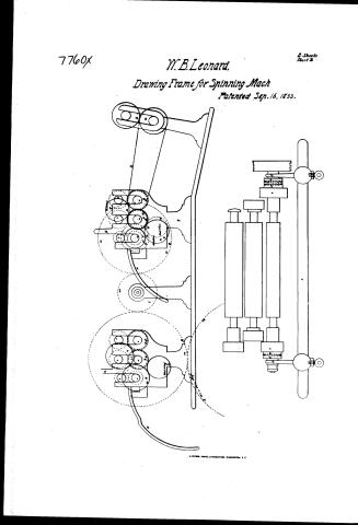
Drawing Frame for Spinning Mach
Patented Sep. 16, 1833.
E. Shanks
Sheet 2
H. PETER, PHOTO-LITHOGRAPHER, WASHINGTON, D.C.
Page 3.
Sept 16 1833
William D. Leonard.
The schedule referred to in these Letters Patent, making part of the same, containing a description in the words of the said William D. Leonard himself of his Improvement in the machinery for carding cotton, called Leonard's improved cotton carding engine.
To all persons to whom these presents may come: I William D. Leonard of Fishkill, in Dutchess County, in the State of New York, do hereby declare: Be it known that I the said Leonard have invented, constructed & applied to use a new & useful improvement in machinery for carding cotton, called Leonard's improved cotton carding engine, specified in the words following (to wit). Note - In the following description the end of the machine upon which the intaking rollers are placed or where the cotton enters the machine is termed the back end, & the end upon which the doffer is placed, or where the cotton is delivered is called the front end -- and the side where the driving pulleys, upon the shaft of the main cylinder are placed is called the pulley side, & the opposite is called the gear side. This machine consists of a framing of iron, three feet & six inches long, with two principal upright posts on each side. These posts are two & a half inches wide, & three eighths of an inch thick, having mouldings or flanges on each edge, projecting five sixteenths of an inch from the face of the posts - a girth of the same width & thickness & flanged in like manner connect these posts at a distance upwards from their feet of five & a half inches. Below these girths the back posts are turned backwards six inches to cause it stand more firmly upon the floor - on the back posts at the height of one foot & eight & three quarter inches are projected backwards at right angles with the posts a piece of equal thickness & width with the post extending fourteen inches, & is supported by a curved brace connecting with the post twelve & a half inches from its foot & the curvature extending to the foot of the post & forming the backward turn of the same, leaving between the post the projected piece is fitted to receive the bearing & bolt to sustain & adjust the shaft of the
Page 4.
140 X7760
broad cylinder, & this piece is slightly projected each side of the slit to give it strength. On the back edge of the post six inches above the last mentioned piece is a semicircular projection extending backwards one & a quarter inch, with a hole in it to receive a crossbar to hold the side frames together. Above this piece the post receives the plate which connects the back & front posts. This plate is of the same thickness & flanged like the posts, is three inches deep or wide, is connected with the girth below by an upright piece of the same thickness with the posts, is three inches wide, flanged, is fourteen & three quarter inches from the back post. Directly over this upright piece, on the top of the plate, a piece is raised one & three quarter inch high, one & a half inch thick, & one & a half inches long, rounded at the ends, containing in the middle a bearing for the shaft of the main cylinder two & three quarter inches long.
The front posts are of equal thickness & flanged like the back posts, rise perpendicularly from the feet receiving the girth from the back post & half upwards from the foot seventeen inches, where a curve commences for a projection forwards which rises in an angular direction until it projects from the front edge of the post five & a half inches, is twenty & a quarter inches high from the foot of the post, when it rises perpendicularly three and a half inches. At the height of eighteen & a half inches from the foot of the post a curve from the back edge commences backwards, until its inclination backwards is two & seven eighths inches when the post assumes its perpendicular direction again. At the height of twenty-three & a quarter inches it receives the top piece connecting these forward & backward projections, which is eight & three quarter inches long on the top face, & two inches wide or deep, leaving a triangular open space between the projections. & top pieces of five & three quarter inches upon its base under the top piece, & a perpendicular of two & a half inches to its apex below which is in a direct line with the front edge of the post below. This top piece is slotted the whole length of the opening to receive the bearing for the doffer, & for adjusting the same is slightly projected against the slit to preserve its strength. The front post is continued upwards to the height of two feet & three & a half inches from
Page 5.
the foot where it receives the plate with a small curvature to strengthen the corners. From the ends of this plate an arch is raised being something more than a semicircle whose radius is eighteen and a half inches, whose center is on the middle of the piece forming the bearing of the main Cylinder. This arch is of the same thickness of the posts and flanged on the outside of each edge. Where the arch joins the back end of the plate a projection is formed outwards from the center two inches, upwards two and a half inches. At the height of eight and a half inches, a similar projection is raised from the arch, these projections are formed by the upper flange of the arch only, leaving open the space between them and the lower or inside flange, also of that section of the arch itself which is between them. These projections are slitted on the top and form the supports for the two back workers whose stripper is adjusted in the space between them. From the front edge of the front post at its junction with the plate, a projection forwards is formed by a double curve: the first of which commences at the top of the piece which sustains the doffer and is formed with a radius of six and a half inches, its center being outwards in a line with the top of the piece which sustains the doffer and its periphery commencing at the front edge of the post. The other curve is formed with the same radius with the center back or inwards. These two curves are made to form a projection whose extreme will be directly over and perpendicular to that which supports the doffer and fifteen and a quarter inches above it. It is two and a quarter inches wide and of the same thickness and flanged like the posts. A top piece is extended from this projection to the arch constituting a rest for the bearing for the shaft of the front worker. This top piece is two and a quarter inches wide and one foot long, an opening is formed between the circular projection the top piece and the arch of an irregular form approaching a triangular but interrupted by the form of the sides and curvatures of the corners. The top piece is slitted over the opening to receive the stand bolt for the front worker and is slightly projected against the slit to preserve its strength. All the above pieces where openings are formed between the posts, the gate and the plate, the upright
Page 6.
piece forming the girth plate under the main cylinder shaft, the plate 8th inch, 8th piece supporting the front worker, one cast with inside flanges for a paneling of wood to rest against to close up the openings. The normal parts of these sides are described as pieces, but they are to be understood as forming one entire piece of casting with only this exception that the arch is formed of two pieces, that one may be removed, to admit the main cylinder with its shaft. The front part of the arch is cast with the framing until it rises one foot from the plate, where it is cut in a line with the center. The remaining part of the arch is flanged only on the outer face, you can from the inside, pass down the standing part of the arch filling the space between the flanges, is bolted firmly to it. The other end of the arch rests on the top of the back end of the plate, 8th plate of iron is fitted & screwed to it on the inside extending upwards beyond the upper projection for the workers forming a back to them 8th the arch & passing downwards on the inside of the plate, to which it is firmly bolted, bringing the flanges on the outside of the arch even with those of the plate so that the whole arch appears to the beholder as one entire piece of casting with the frame. These sides are supported by beams of wood of suitable thickness, to fill the space between the flanges of the frame, where they are placed & are all two feet & four inches long & secured by joint bolts. The first piece is between the back legs on a level with the girth at the lower edge 8th 8th 8th half inches wide. The second is placed at the back extreme of the projection for the intaking rollers, 8th three 8th half inches wide. The third is between the front posts the bottom edge level with the feet 8th fifteen inches wide & double bolted. In addition to these beams the sides are supported by an iron rod passing through the holes in the semicircular projection above the breast cylinder screwed firmly by a nut on the outside to a shoulder on the inside, & also by a piece of casting passing from arch to arch just forward of the projection for the upper worker and held by a bolt passing through the arches into the piece in which the female screw is cut, also by a piece of casting two 8th half inches wide extending across the frame, bolted to the front of the projections supporting
Page 7.
the front worker, the front face of this piece may be ornamented according to fancy. When these several parts are adjusted a frame is formed. Two feet from inches wide on the inside. To this frame the following pieces or parts are attached for the purposes named, a stand is bolted to the back part on the gear side on the back end of which is the step for the room shaft. This stand is placed eleven inches high from the foot of the post. It is seven inches long. On each projection for the intaking breast rollers, a stand ten inches long is bolted on the lower extremity back of which is the bearing of the unwinding roller which turns the bat roller to deliver its cotton to the cards. Over this at the back end a grooved upright is projected to guide and hold in place the bat roller, as it diminishes in diameter by the unwinding of the batting. They are on the inside, twice nine and a half inches. On the front end of this stand is the bearing for the intaking rollers projected upwards and grooved for a guide to keep the top roller in place. On the outside of this stand, on the pulley side of the frame, a stand is bolted with its stand for a stud wheel to give motion to the unwinding roller. A piece of iron polished on its upper surface is bolted to the top of these stands extending across the frame filling the whole space between the unwinding and the intaking rollers for the cotton to slide on as it leaves the bat roller. Bearings with caps, screws and bolts are placed on the same projection over the slits for the breast cylinder shaft to turn in. The poppet heads are passed through the slits in the projections on the arch and the feet of their screws, pass the inside arch and nut on each side, adjust their height and a screw through each side of the projections, adjust them to the stripper. These poppets are seven and a half inches long, form a bearing in their heads for the shaft of the workers. A like poppet six inches long is passed through the arch intermediate between these with nuts to raise and depress it to open the main cylinder, with bearing in the heads for the back stripper. Thirteen steady pins are then inserted into the top of the arch rising two and a half inches in a line with the center at a distance of two and a half inches from each other to keep the flats in place.
Page 8.
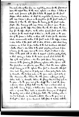
On each side of these pins are regulating screws for the flats to rest upon to adjust them to the main cylinder. A stand is bolted to each arch forward of the flats to hold the levers for the front stripper which sustains its shaft. It is regulated by screws. A bearing with caps & screws is placed on the projections for the front worker, & is bolted to it through the slit & forms the bearing for the front worker shaft. The bearings with caps & screws are placed upon the projected pieces for the doffer & are bolted through the slit & form the bearings for the doffer shaft. On the outside of each front post a bolted stand for the crank shaft to turn in. On the plate on the gear side of the frame is bolted a stand with its stud for the stud wheel which communicates motion to the front worker & the doffer. A stand is also bolted to this plate with its stud to hold a stud wheel having a pinion on its hub to give motion to the last mentioned stud wheel. Another stand is also bolted to this plate projecting outwards to form a bearing for the upper end of the worm shaft. A stand is also bolted to this plate with its stud to support a friction pulley. Lastly, a steel spring is bolted to the inside of each plate to hold the top of the cord pitman. All these parts & pieces being properly secured to the framing, the following cylinders, rollers, & pieces with their furniture are placed upon them. First the main cylinder shaft having on it the cylinder three feet in diameter, three feet four inches long, and on its pulley end a loose pulley twelve inches in diameter, three & a half inches on the face, next a fast pulley of like dimensions; then between this & the frame a flanged pulley, sixteen inches in diameter between the flanges, four & a half inches on the face. On the gear end of this shaft there is next the frame a pinion wheel of thirty teeth & on the end is a bevel wheel of sixty teeth having its face or toothed side inward. The unwinding roller is of wood, three inches in diameter, having on its shaft on the pulley end a wheel of thirty-five teeth. The intaking roller is one & a half inches in diameter is fluted, & on the gear end of its shaft a wheel of one hundred teeth fitted to match with the
Page 9.
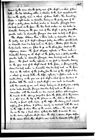
turned by the worm. On the pulley end of this shaft is a wheel of eleven teeth. The top intake roller is similar to the last described, it has on the pulley end a wheel of eleven teeth. The breast cylinder is eight inches in diameter having on the pulley end of its shaft a pulley seven and a half inches in diameter flanged down a half inch on the face. The two back rollers are six inches in diameter having on the gear end of their shafts a pulley four and three quarter inches in diameter flanged down one and a half on the face. The stripper between them is three inches in diameter that on the pulley end of its shaft a flanged pulley six and three quarter inches in diameter down and a half inch on the face. Thirteen flats two and a half inches wide are fitted to go on the steady pins direct on the adjoining screws. The front stripper cylinder is three inches in diameter having on its shaft at the pulley end a pulley six and three quarter inches in diameter flanged down and a half inch on the face. The front worker cylinder is one foot in diameter having on the gear end of its shaft direct to the frame a flanged pulley seven and a half inches in diameter down and a half inch on the face. And on the outside of this pulley, from the end of the shaft it has a wheel of ninety teeth, the doffer cylinder is fifteen inches in diameter, having on the gear end of its shaft a wheel of one hundred and fourteen teeth. The comb or crank shaft is one inch in diameter, with two cranks of one inch sweep having on its pulley end a pulley of six inches diameter flanged down and a half inch on the face — connected with the cranks are two curved pitmen extending from the cranks to the springs projected from the plates, which they receive in a slot near the top of the pitmen in other slots in the pitmen directly in front of the center of the doffer. The clearing comb is secured passing from pitman to pitman nearly in contact with the cards on the doffer to clear them of the carded cotton. The worm shaft has on the top a bevel wheel of thirty-two teeth to match the one on the main cylinder shaft, where the step a worm, to give motion to the worm wheel, this shaft is one inch in diameter and two feet
Page 10.
X7760
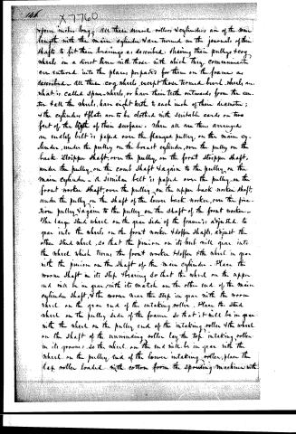
from inches long. All these small rollers & cylinders are of the same length with the main cylinder & are turned on the journals of their shafts to fit their bearings as described, sharing their pulleys & cog wheels in a direct line with those with which they communicate. They are entered into the places prepared for them on the frame as described. All these cog wheels, except those termed bevel wheels, are what is called spur wheels, or have their teeth outwards from the center. All the wheels have eight teeth to each inch of their diameter; & the cylinders & flats are to be clothed with suitable cards on two feet of the length of their surface. When all are thus arranged an endless belt is passed over the flanged pulley on the main cylinder, under the pulley on the breast cylinder, over the pulley on the back stripper shaft, over the pulley on the front stripper shaft, under the pulley on the comb shaft & again to the pulley on the main cylinder. A similar belt is passed over the pulley on the front worker shaft, over the pulley on the upper back worker shaft, under the pulley on the shaft of the lower back worker, over the friction pulley & again to the pulley on the shaft of the front worker. The large stud wheel on the gear side of the frame is adjusted to gear into the wheel on the front worker & doffer shafts, adjust the other stud wheel, so that the pinion on its hub will gear into the wheel which turns the front worker & doffer & the wheel in gear with the pinion on the shaft of the main cylinder. Place the worm shaft in its step bearing so that the wheel on the upper end will be in gear with its match on the other end of the main cylinder shaft, & the worm wheel the step in gear with the worm wheel on the gear end of the intaking roller. Place the stud wheel on the pulley side of the frame so that it will be in gear with the wheel on the pulley end of the intaking roller & the wheel on the shaft of the unwinding roller lay the top intaking roller in its groove, so the wheel on the end will be in gear with the wheel on the pulley end of the lower intaking roller, place the lap roller loaded with cotton from the spreading machine with
Page 11.
X7760
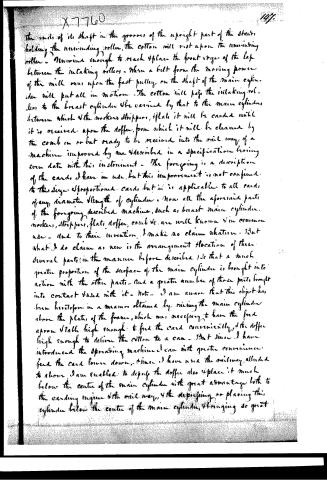
the ends of its shaft in the grooves of the upright part of the stand, holding the unwinding roller, the cotton will rest upon the unwinding roller. Unwound enough to reach 4 places the front edge of the lap between the intaking rollers. When a belt from the moving power of the mill runs upon the fast pulley on the shaft of the main cylinder will put all in motion. The cotton will pass the intaking rollers to the breast cylinder & be carried by that to the main cylinders between which & the workers strippers, flats it will be carried until it is received upon the doffer, from which it will be cleaned by the comb in or but ready to be received into the rail way of a machine improved by me & described in a specification having even date with this instrument. The foregoing is a description of the cards I have in use, but this improvement is not confined to this size & proportioned cards, but is applicable to all cards of any diameter & length of cylinder. Now all the aforesaid parts of the foregoing described machine, such as breast main cylinder, workers, strippers, flats, doffer, comb &c. are well known & in common use. And to their invention, I make no claim whatever. But what I do claim as new is the arrangement & location of these several parts (in the manner before described) so that a much greater proportion of the surface of the main cylinder is brought into action with the other parts. And a greater number of these parts brought into contact & used with it. Note. I am aware that this object has been heretofore in a measure obtained by raising the main cylinder above the plates of the frame, which was necessary to have the feed apron & table high enough to feed the card conveniently, & the doffer high enough to deliver the cotton to a can. But since I have introduced the spreading machine I can with greater convenience feed the card lower down, & since I have used the railway alluded to above I am enabled to depress the doffer also & place it much below the center of the main cylinder with great advantage both to the carding engine & the rail way, & the depressing or placing this cylinder below the center of the main cylinder, & bringing so great
Page 12.
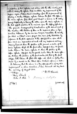
a proportion of that cylinder into action with the other carding parts without raising the cylinder itself constitutes my improvement of this engine, again I derive much advantage from the improvement of placing a worker & stripper cylinder between the flats & the doffer on the main cylinder from which great benefit is derived in the carding process, especially in leaving the cotton upon the main cylinder in the last possible position to be received upon the doffer cylinder. The general arrangement of, & combination of the several parts of this machine & the location of them on the improved plan as before described & claimed by me are new & useful & constitute the novelty for which a Patent is now prayed & are more fully illustrated by reference to the plate appended to this specification upon which four cards are represented at work with my improved railway drawing head. A. shows the position of the journal or center of the main cylinder shaft. B. the feed rollers depressed nine & a quarter inches below. The main cylinder C. shows the position of the doffer cylinder depressed six & a quarter inches below the main cylinder. D. shows the position of the front worker, & E. that of the front stripper both between the flats & the doffer all which are fully illustrated by a model in the Patent office to which reference is made. In testimony that the above is a true specification of my said improvement as above described, I have hereunto set my hand this 29th day of August 1833.
W. O. Seward
Witnesses:
Henry Schenck
Elisha A. Abel
Drawing on back folio
[8396.]
[4306 words]
Published accounts: journal notice
Notice in the monthly list of patents, with remarks
Journal of the Franklin Institute, new ser., vol. 13 (1834), p. 247 · View the page
With Remarks and Exemplifications, by the Editor. [Continued from p. 182.] 28. For an improved Cotton Carding Engine; William B. Leonard, Fishkill, Dutchess county, New York, September 16.
Remarks. After describing the carding engine with much minuteness, the claim is made in the following words, which is all we can afford to give. "Now, all the aforesaid parts of the foregoing described machine, such as breast, main cylinder, workers, strippers, flat, doffers, comb, &c. are well known and in common use, and to their invention I make no claim whatever; but what I do claim as new is the arrangement and location of these several parts, in the manner before described; so that a much greater proportion of the surface of the main cylinder is brought into action with the other parts.
About this record
- Patentee
- DATAMP
- Date
- the Name and Date index of patents, DATAMP, USPTO records
- Invention
- DATAMP
- Listed in
- the Name and Date index of patents, DATAMP, USPTO records, Jim Shaw's X-patent list, the Journal of the Franklin Institute, Burke's List of Patents (1847)
- Burke's 1847 Patent Office list gives the same patent.