

Drawings and documents
USPTO scan
The patent as scanned by the USPTO
-
 Page 1
-
 Page 2
-
 Page 3


U.S. Patent and Trademark Office · Google Patents
Show the transcription Hide (711 words)
Machine transcription (LightOnOCR) of the pages as scanned by the USPTO, most of them the handwritten copies made when the records were restored after the 1836 fire. Not checked; it can misread handwriting, so compare it with the scan.
Page 1.
7799X
W. Easby.
Coffer Dam.
Patented Nov. 19, 1833.
Page 2.
William Easby 7799X Nov 19, 1833
The schedule refers to in this Letter Patent and making part of the same containing a description in the words of the said William Easby himself of his improvement in the construction of Coffin Dams.
It is known that I William Easby of the City of Washington District of Columbia have made a new and useful improvement in the construction of Coffin Dams called Easby's Coffin Dams which is described as follows. Reference being had to the annexed drawings—
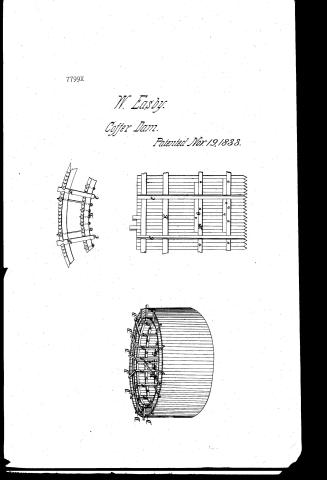
This dam is constructed in the following manner. Wooden piles of a suitable length and strength are driven in by a pile driving machine in a circular form or many-sided polygon, enclosing the space where the fence or other work is to be built inside. These piles are shot at their points with iron or steel, and their heads protected by iron rings. When cut down to their proper height, they are also tongued and grooved so as to fit into each other perfectly. In order to form the circle it will be necessary first to drive a pile near the center of the intended circle, marked A, in the drawing. On this pile place a beam or boom B, turning on a collar, by which the radius of the circle will be described. Piles C will then be driven at about one foot within the periphery of the dam and at about 8 feet apart, another circle D will be formed at the distance of about 10 feet outside of the first driving in piles in the same manner as the first. The heads of both circles will then be cut off at about 4 feet above high water at common tides. The frame being now finished is ready to receive the pile driving engine. At circle B similar to the upper inner one will be secured to the outside of the inner line of piles perpendicular.
Page 3.
parallel to the one above mentioned at two water marks. The piles being properly prepared with their cages converging to the center of the circle, the driving may be commenced: care however must be taken that the first pile be driven perfectly vertically and secured to its place by turnails passing through its head and the upper rim, the next pile will be inserted into the groove of the first, driven home and secured. After the dam is enclosed the water may be pumped out to 10 ft below the surface, at which point a rib of oak 6 to 12 inches thick may be secured on the inside of the dam or inner circle by large screw eye bolts H, after which the water may be pumped out to 10 feet and another rib I inserted. The reason for placing these ribs as directed is not only to regulate the piles and strengthen the dam but in case any pile should be out of its place it can be brought into its place again by the screw bolts. Should any obstruction occur it will be necessary to be provided with a good oak pile having a steel shaped point with its head well hooped. This pile is to be used to make way for the copper dam pile to be driven. When the bottom or foundation is poor one tier of piles only is necessary. When two ranges of piles are deemed necessary, the proof will be the same the loose mud must be taken from between the circles & the circles be secured by screw bolts passing from the exterior circle to the interior circle to prevent them from being separated by the packing between them.
That I claim as my invention and desire to secure by Letters Patent is the peculiar construction of the before described Copper dam, but I particularly claim the circular figure of the dam, whether a perfect circle, oval or a polygonal of many sides disposing with braces and giving it great strength.
Wm. J. Elliot
William Crosby
Samuel L. Mathews
(1875)
Published accounts: journal notice
Notice in the monthly list of patents, with remarks
Journal of the Franklin Institute, new ser., vol. 13 (1834), p. 265 · View the page
17. For an improvement in the Construction of Coffer Dams; William Easby, Washington, District of Columbia, November 19.
Remarks. VOL. XIII.-No. 4.-APRIL, 1834. 34 The coffer dam for which this patent is obtained is to be either circular, oval, or a many sided polygon. The manner of forming it does not differ in any essential particular from that commonly pursued. The patentee says, " I particularly claim the circular figure of the dam, whether a perfect circle, oval, or a polygon of many sides; dispensing with braces, and giving it greater strength." Different forms have been given to coffer dams, suggested, of course, by the shape of the pier which is to be erected within them; we are not aware, however, that they have ever been made circular or oval; there are, in fact, but few cases in which circular coffer dams would be admissable, as it is a point of importance that the area within the dam should be no greater than is required for the laying the foundation, as, otherwise, the quantity of water to be discharged would be increased, and other evils encountered; there would, however, be a manifest advantage derived from the form, especially where the depth, and, consequently, the pressure, was great.
About this record
- Patentee
- DATAMP
- Date
- the Name and Date index of patents, DATAMP, USPTO records
- Invention
- DATAMP
- Listed in
- the Name and Date index of patents, DATAMP, USPTO records, Jim Shaw's X-patent list, the Journal of the Franklin Institute, Burke's List of Patents (1847)
- Burke's 1847 Patent Office list gives the same patent.