

Drawings and documents
USPTO scan
The patent as scanned by the USPTO
-
 Page 1
-
 Page 2
-
 Page 3
-
 Page 4
-
 Page 5


U.S. Patent and Trademark Office · Google Patents
Show the transcription Hide (1,249 words)
Machine transcription (LightOnOCR) of the pages as scanned by the USPTO, most of them the handwritten copies made when the records were restored after the 1836 fire. Not checked; it can misread handwriting, so compare it with the scan.
Page 1.
7834X
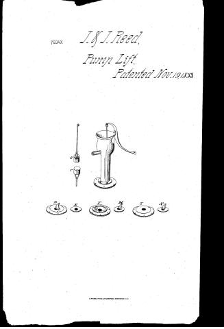
J. H. J. Reed,
Pump Lift,
Patented Nov. 19, 1833.

Page 2.
X7834 Nov. 19, 1833 163.
Joseph Reed & Joseph Reed
Fellow Patent
The Schedule referred to in these Letters Patent and making part of the same containing a description in the words of the said Joseph Reed & Joseph Reed themselves of their improvement in the Cast Iron Pumps.
The principal parts of the machine consist of a perpendicular hollow cylinder with its flange - bottom plates - valves - piston all made of cast iron or other suitable metal and iron or brass, lead pipe, screw & bolt. The body of the pump or cylinder is about two feet long with a cavity or bore from two to four inches in diameter according to the quantity of water required to be raised. At the bottom of the cylinder there is a horizontal projection or flange about eight inches in diameter. The piston of the pump is about three inches long of a size adapted to the bore of the cylinder and is grooved on its circular side for receiving rope yarn or any other packing substance which may be required to make the piston more sufficiently close and tight. The bottom part of the piston to the height in the centre of about one inch and a half from near its circular edge to a hole passing, then the piston is made concave in the form of the upper part of a funnel inverted. The valve in the piston rests horizontally on a shoulder about one eighth of an inch wide, and is placed at the lower end of the hole when the said hole opens into the concave bottom part of the piston. A rod of suitable size & length is attached to the upper side of the piston, and the top part connected by a joint with the lever or brake. The parts of the pump beneath the flange of the cylinder are adjusted in three different modes as may be preferred. In the first mode a plate about twelve inches
Page 3.
in diameter and of a suitable thickness for the strength required, with a hole in the centre about one inch & a half diameter is placed under the horizontal flange of the cylinder. This plate has a circular elevation on the upper side between the centre and circumference, about one inch wide for the purpose of holding more firmly the screws which pass thro' this elevated part from the flange and is depressed within the elevation so as to receive within its bed another plate about four inches in diameter and half an inch in thickness. This small plate has a hole in the centre, corresponding with that in the large or main plate beneath, with a valve attached on the upper side. A lead pipe passes from the water thro' the hole in the large plate and about one half inch thro' is turned over nearly at a right angle between the plates and covered with a piece of leather of the same width. The central part of the upper side of the small plate is raised about one-eighth of an inch and being of the same diameter with the bore of the cylinder enters & forms a close joint therein. That part of the plate not raised is covered with leather of such thickness as to make the surface under the flange of the cylinder level and all the parts compact and tight when brought together by the screws which pass through the said flange & the thick & elevated part of the large or main plate. In the second mode, the lead pipe passes thro' a hole about one & a half inch over, in the centre of a plate nearly eight inches in diameter and half an inch in thickness & turned over as in the preceding mode. The plate is inclosed or embedded centrally and horizontally in the underside of another plate about one foot in diameter so that the under sides of both plates may form an even or level surface. A hole is made in the large or main plate of the same size with the one in the
Page 4.
the small plate beneath & directly over the same having, a valve attached thereto on the upper side, the parts are secured and made compact by screws which pass through the flange of the cylinder & the main plate and screw into the small plate. In the third mode, a plate about twelve inches diameter having a hole in the centre of the size above mentioned is placed horizontally under the flange of the cylinder. The lead pipe passes through this aperture and is turned down nearly at a right angle so as to fill a counter sink in the plate to a level surface. Another plate about half an inch thick and of the requisite diameter with a hole in the centre to correspond with that in the plate last above mentioned is inserted in the lower end of the cylinder having its lower side on a level with the lower side of the horizontal flange of the cylinder. In putting the parts together, the screws pass through the flange & screw into the main plate. The lower valve which is of the same form and operates in the same way in all the different modes of arranging the plates, consists of a horizontal and circular plate about one third of an inch in thickness with a diameter a little exceeding that of the hole over which it is placed and of another plate of nearly the same thickness, placed on the upper side and across the diameter of the horizontal plate its widest sides being at a right angle with the same. The latter plate is of an oval form at the top and its narrow sides or edges decline about ten degrees from a perpendicular toward the side where the valve opens to its greatest extent. This valve beside opening in the ordinary way may be opened & kept open as long as is necessary by raising the brake of the pump & bringing down the concave or tunnel like surface of the bottom part of the piston, upon & against that side of
Page 5.
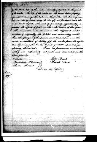
of the steel top of the valve, directly opposite to the joint of the valve. The top of the valve at the same time pressing against & raising the valve in the piston. In this way water in the cylinder may be let off at pleasure, and the important object attained of guarding effectively against the effects of frost in the cold season of the year.
The improvements claimed are the different modes or methods of adjusting the plates and connecting with them the flange of the pump and lead pipe, and the mode or method of letting off the water from the cylinder by raising the brake to its greatest extent and opening the valves. Said improvements are claimed as they are respectively set forth and described in this specification.
Witnesses
Nathaniel Whitman
Aaron Hobart
Vigie Reed
Patrick Reed
(Gran portfolios)
Exd.
M.96
1/110 w-62
Published accounts: journal notice
Notice in the monthly list of patents, with remarks
Journal of the Franklin Institute, new ser., vol. 13 (1834), p. 325 · View the page
59. For improvements in the Pump for raising Water; Jesse Reed, Marshfield, and Josiah Reed, East Bridgewater, Plymouth county, Massachusetts, November 19.
Remarks. The pump described is intended to be made of cast iron in its upper part, and to have a tube of lead to extend into the well; particular modes of arranging the valves are described, principally with a view of rendering the junctions tight, and of allowing the lower valve to be opened permanently, that in frosty weather the water may escape through it. Three different modes of connecting the pipes and valves by plates of iron, are described, and the claims are to "the different modes of adjusting the plates, and connecting with them the flanch of the pump and lead pipe; and the mode or method of letting off the water from the cylinder." The patentees have very properly confined themselves to the particular arrangements which they have described, and to these they have a right; we do not, however, think them of much importance, not being aware of any existing difficulty which they have overcome, although the patentees, of course, think differently. There have been modes devised for opening the lower valve in metal pumps, but in cold climates such pumps ought not to be employed for common purposes, their extreme liability to freeze rendering them very troublesome: and even in warm weather wood is to be preferred by those who do not wish to drink warm water.
About this record
- Patentee
- DATAMP
- Date
- the Name and Date index of patents, DATAMP, USPTO records
- Invention
- DATAMP
- Listed in
- the Name and Date index of patents, DATAMP, USPTO records, Jim Shaw's X-patent list, the Journal of the Franklin Institute, Burke's List of Patents (1847)
- Burke's 1847 Patent Office list gives the same patent.