

Drawings and documents
USPTO scan
The patent as scanned by the USPTO
-
 Page 1
-
 Page 2
-
 Page 3
-
 Page 4
-
 Page 5


U.S. Patent and Trademark Office · Google Patents
Show the transcription Hide (1,322 words)
Machine transcription (LightOnOCR) of the pages as scanned by the USPTO, most of them the handwritten copies made when the records were restored after the 1836 fire. Not checked; it can misread handwriting, so compare it with the scan.
Page 1.
7843X
I. M. G. TRUMAN.
Lamp.
Patented Nov. 19, 1833.
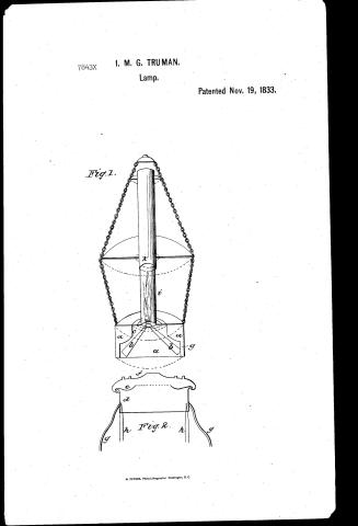
Fig. 1.

Fig. 2.
N. PETERS, Photo-Lithographer, Washington, D. C.
Page 2.
Nov 19 1833
Joseph M. Truman & George Truman Partnership Proprietors
Letters Patent
The schedule referred to in the Letters Patent and making part of the same contains a description in the words of the said Joseph M. Truman and George Truman themselves of their improvement in Samps which are used as Spirit gas Samps.
We, the undersigned, do hereby declare that the said Joseph M. Truman and George Truman, being in the County of Philadelphia, have invented an improved Samps for the burning of oil, tallow, spirits, or any of the combustible, solid, semi-fluid, or fluid components usually burnt which Samps are constructed by us and denominated the oil or Spirit gas Samps, and intend to employ it for illuminating streets, stores, public buildings, houses, or other places where artificial light may be required, and we declare by these Letters that the following is a full and clear description thereof, and since being had to the drawings which accompany and make a part of this specification. We call our Samps a Gas Samps because there is a part of it which we denominate the patent or Gas generator in which the vapors arising from the burning tallow or such as is so decomposed and prepared for the immediate and perfect combustion with mixture with a due proportion of pure plain air in a way to be presently described. By "t" in the accompanying drawings is a lateral section somewhat in perspective of the whole apparatus in one of its forms showing a Samps which may be suspended in a store or the like, and in the cup or reservoir which is to contain the oil or other material it has a bottom and sides like the common street Samps but has any other number of tubes or burners for containing which tubes are inclined to the bottom of the Samps by their lower edges whilst they incline towards each other at their upper ends and bring their flames when ignited, into contact with each other or
Page 3.
nearby. C is the part called by us the rotor or Generator in Fig. 2, a section of this is seen of the full size. Sometimes such by as. A, is a ring of brass or other metal which may be about three fourths of an inch thick, e.g., are the concave pieces of metal with their concave sides turned towards each other thus leaving a chamber or space between them. They are both edged, or otherwise joined to the ring A. The upper plate F, has a round or other shaped orifice in its centre generally of from three eighths to half an inch in diameter—in inner edge being turned up as shown in the sketch. Sometimes instead of one we make several orifices, their number and form admitting of considerable variation whilst their capacity or area is a point of considerable importance. In the lower plate C, a single orifice is made which may be an inch or more in diameter or of such size as will take in the nick or nicked at the upper end of the tube or bunsen. Although we prefer to make the rotor in the manner described or nearly so we do not confine ourselves thereto but vary this also in different ways. Sometimes we use a single plate F, omitting the plate E, Fig. 2 in which case it may be flat or concave, instead of conical style having the holes or slots in the centre. As the lower edge of the ring A is not intended to come into contact with the oil or other material in the reservoir of the lamp, the air of the atmosphere is freely admitted under it to assist in mixing with the gas, passed in the rotor or generator and effect its combustion but the ring A, may be perforated with holes entirely surrounding it below the edging of the plates. Y. g. rep—present legs sometimes used to support the rotor or generator within the reservoir. When tallow or other hard semi-fluid substance is employed these legs should be made of stout copper to serve as heaters that being the best conductor among the cheaper metals. Instead of these legs we commonly use spring pieces h. h. or wires & pup into sockets rising from the inside of the reservoir or employ other convenient means of supporting the rotor. It is well however to be able to raise or lower it for reasons which will presently
Page 4.
appears and thus the spring and socket readily allow. The flame which is to ascend through the orifice in the plate is to be surrounded by a glass chimney such as is ordinarily used with lamps but this is to be surrounded by a metallic or other tube or chain which is to be lower end of which the glass chimney passes. This arrangement will be described in illustration to one in employment is of peculiar importance in the Sample which we have described. In Samples of the ordinary size the length of the illuminator should be from twelve to sixteen inches and of about two inches in diameter varying of course with the size of the Sample and the consequent enlargement or diminution of the flame. When this lamp is to be used the wicks are to be lighted and shown to be drawn up as to burn with a full large flame. The retort or generator is then brought down through any to a distance of from one half to one fourth of an inch from the wick, when a flickering blue flame will ascend through the orifice or orifices of the upper plate when more than one plate is employed, the light from which will be very full and without smoke. The glass chimney is then to be placed on the frame resting on the generator between small projecting rivets this will produce a strong yellow flame rising to the top of the chimney with much smoke. The illuminator is then added which produces a clear brilliant stream of a blue flame ascending to the height of from four to six inches and without any smoke to be seen. We have thus fully described the general construction of one the manner of using our Sample and have indicated some of the numerous changes which may be made in it in more matters of convenience whilst the principle of its construction and action will remain the same.
What we claim as our invention is the employment of that part which is designed to be the retort and in the way herein described and consisting of one or more plates to be let down upon the flame and we claim the lengthening out of the glass chimney by means of the illuminator without which the combustion will not be rendered
Page 5.
1843
effect. It will be seen that although this illuminator may have some resemblance to a chimney or tube for carrying off smoke, which is in common use yet in our Sample it is applied to effect an illumination in any different object, namely the entire destruction of the smoke by the perfect combustion of the carbonaceous matter of the gas. We claim this therefore not alone as a better chimney but in combination with the generator and glass chimneys for the purpose hereinbefore set forth in a Sample of our Construction.
Witnesses
Mr. M. Michael
Wm. C. Master
George T. T.
London, Portcullis 7339
Published accounts: journal notice
Notice in the monthly list of patents, with remarks
Journal of the Franklin Institute, new ser., vol. 13 (1834), p. 327 · View the page
64. For an Oil or Spirit Gas Lamp; Joseph M. Truman and George Truman, Penn township, county of Philadelphia, Pennsylvania, November 19.
Remarks. This lamp is intended principally for streets, public buildings, halls, &c. where a brilliant and steady light is required. It is constructed for the combustion of oil, tallow, or other articles capable of being burnt in lamps. The inventors denominate it a gas lamp, because the upper part of the reservoir for oil, &c. forms what they denominate a retort, in consequence of its being so constructed that the flame of the burning wick shall heat it sufficiently to decompose the oil, and partially convert it into gas. The flame which ascends from the reservoir is surrounded by a glass chimney, in the usual way; and this glass chimney is surmounted by a metallic tube, into the lower part of which the glass enters. The metallic tube extends above the glass, to the height of from twelve to sixteen inches, and is called the illuminator, as, by its aid, the flame may be made to ascend to nearly the top of the glass chimney, and to afford a very brilliant illumination, without any smoke; this illuminator appears to be one of the most essential features of the lamp. The patentees say "What we claim as our invention is the employment of that part which we denominate the retort, used in the way herein described, and consisting of one or more plates to be let down upon the flame; we also claim the lengthening out of the glass chimney by means of the illuminator, without which the combustion will not be rendered effective."
About this record
- Patentee
- DATAMP
- Date
- the Name and Date index of patents, DATAMP, USPTO records
- Invention
- DATAMP
- Listed in
- the Name and Date index of patents, DATAMP, USPTO records, Jim Shaw's X-patent list, the Journal of the Franklin Institute, Burke's List of Patents (1847)
- Burke's 1847 Patent Office list gives the same patent.