

Drawings and documents
USPTO scan
The patent as scanned by the USPTO
-
 Page 1
-
 Page 2
-
 Page 3


U.S. Patent and Trademark Office · Google Patents
Show the transcription Hide (645 words)
Machine transcription (LightOnOCR) of the pages as scanned by the USPTO, most of them the handwritten copies made when the records were restored after the 1836 fire. Not checked; it can misread handwriting, so compare it with the scan.
Page 1.
7882X
T. F. Anderson,
Water-Wheel Gate.
Patented Dec. 23, 1833.

M. PETERS, PHOTO-LITHOGRAPHER, WASHINGTON, D. C.
Page 2.
Dec 23, 1833
Timothy P. Anderson of Hardwick, county of Worcester, commonwealth of Massachusetts
Letters Patent
The Schedule referred to in these Letters Patent, and making part of the same, containing a description in the words of the said Timothy P. Anderson himself of his improvement in the economy of Water power by means of a graduated spout.
To all people to whom these Presents shall come
Be it Known, that I Timothy P. Anderson of Hardwick in the county of Worcester and commonwealth of Massachusetts, Mechanist have invented a new and useful improvement in the economy of water power by means of a graduated spout or trough, and that the following is a full and exact description of the construction & operation of the same as invented or improved, by me & specified in the words following. So Help
The flume containing the water may be constructed in the usual manner. The shaft of the water wheel stands perpendicularly & near the lower end of it, are firmly attached and fastened. The buckets which I have made use of, are about twelve inches in width and placed upon the shaft in this way: they lay over each other at the ends and the space between the laps is about two inches.
The spout conducting the water from the flume is as wide as the buckets and passes round the shaft in such manner that the upper sides of the buckets compose the lower side of the spout. From the point at which the water strikes the first bucket, the spout begins to diminish in its depth (its width being uniform) until it has shaped entirely round the wheel. The top and sides of the spout are made sufficiently firm to withstand the pressure of the water. The only place for the water to escape from the spout is thro' its laps on the buckets. As the spout diminishes in its depth the pressure of the water is as great on the last as on the first bucket & is upon all the buckets at the same time.
Page 3.
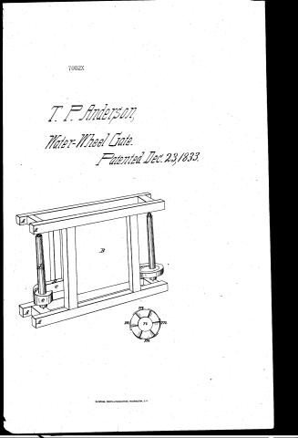
Explanation of the Drawing
AAAA Frame of the Flume. Bc Flume. d shaft e e spout, conducting the water to the wheel. gg Slips or appliances of the wheel, or shaft. mmm Buckets attached to the shaft. V contained in the spout e e. Operation of the Machine—When the water is permitted to pass out of the flume into the spout e e the whole shaft is immediately filled and the pressure of the water upon the buckets puts the shaft in motion.
There is a resemblance at first sight between my wheel and a common tub wheel, but the difference consists in the manner in which the water leaves the buckets. In the tub wheel the water leaves the buckets at almost a right angle, but in mine it leaves them in almost directly the opposite direction to its course. And in this way as the water flows in a direction nearly opposite, parallel with the buckets and cannot escape, excepting between them, the first action of the water is direct impulse and that produced by the contrary direction is reaction, and these, it is believed, make a valuable saving of water power.
All I claim as my invention is the graduated spout or trough as above described, if its applicability as applied by me.
Witnesses
John B. Davis
Lewis Bigelow
Timothy P. Anderson
Drawing
650 22-82
Published accounts: journal notice
Notice in the monthly list of patents, with remarks
Journal of the Franklin Institute, new ser., vol. 13 (1834), p. 397 · View the page
31. For an economical mode of Applying Water Power; Timothy P. Anderson, Hardwick, Worcester county, Massachusetts, December 23.
Remarks. The water is to be conducted through a close trough, or spout, from the lower side of a flume, so as to surround the water wheel. This wheel stands on the lower end of a vertical shaft, and consists of six leaves, or buckets, formed like those of a smoke jack, having openings of about two inches, and lapping over each other so as to deliver the water in a direction nearly horizontal. The end of the spout which surrounds the wheel, is to decrease in height in its circuit, and this, it is strangely enough imagined, will influence the pressure of the water on the wheel. If the wheel was placed in an opening in the bottom of the flume, it would be more simple and equally efficient, but still it would not " make a valuable saving of water," as the patentee believes his will.
About this record
- Patentee
- Jim Shaw's X-patent list
- Date
- the Name and Date index of patents, USPTO records, Burke's List of Patents (1847)
- Invention
- the Name and Date index of patents
- Listed in
- the Name and Date index of patents, USPTO records, Jim Shaw's X-patent list, the Journal of the Franklin Institute, Burke's List of Patents (1847)
- The sources give different dates; the date shown is the one most of them agree on.
- The Franklin Institute's journal confirms the date shown.
- Burke's 1847 Patent Office list gives the same patent.