

Drawings and documents
USPTO scan
The patent as scanned by the USPTO
-
 Page 1
-
 Page 2
-
 Page 3


U.S. Patent and Trademark Office · Google Patents
Show the transcription Hide (824 words)
Machine transcription (LightOnOCR) of the pages as scanned by the USPTO, most of them the handwritten copies made when the records were restored after the 1836 fire. Not checked; it can misread handwriting, so compare it with the scan.
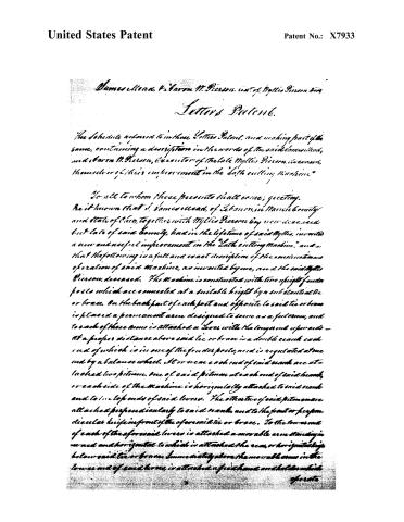
Page 2.
United States Patent
Patent No.: X7933
James Mead & Aaron M. Pierson, exr. of Myllis Pierson, decd.
Letters Patent.
The Schedule referred to in these Letters Patent, and making part of the same, containing a description in the words of the said James Mead, and Aaron M. Pierson, executor of the late Myllis Pierson, deceased, themselves or of their improvement in the “Lath cutting Machine.”
To all to whom these presents shall come; greeting.
Be it known that I, James Mead, of Lebanon, in Massachusetts and State of Ohio, together with Myllis Pierson by now deceased but late of said County, had in the lifetime of said Myllis, invented a new and useful improvement in the “Lath cutting Machine,” and so, that the following is a full and exact description of the construction and operation of said Machine, as invented by me, and the said Myllis Pierson, deceased. The Machine is constructed with two upright fender posts which are connected at a suitable height by a substantial tie or brace. On the back part of each post and opposite to said tie or brace is placed a permanent arm designed to serve as a fulcrum, and to each of these arms is attached a lever with the long end upwards — at a proper distance above said tie or brace is a double crank each end of which is in one of the fender posts, and is regulated at one end by a balance wheel. At or near each end of said crank are attached two pitman. One of said pitman at each end of said crank, or each side of the Machine is horizontally attached to said crank and to the top ends of said levers. The other two of said pitman are attached perpendicularly to said crank, and to the front or perpendicular knife in front of the aforesaid tie or brace. To the lower end of each of the aforesaid levers is attached a movable arm standing in a nut and horizontal to which is attached the rear, or horizontal knife below said tie or brace. Immediately above the movable arm in the lower end of said levers, is attached a feed hand and holder which operate
Page 3.
United States Patent
Patent No.: X7933
operate on a ratchet wheel between the ends of the perpendicular knife and each fender post. These ratchet wheels are at the ends of a roller on which are placed two or more pinion wheels.
Above the back of the perpendicular knife to movable levers to the aforesaid tie, or brace, resting on arms or fulcrums on the roller aforesaid; at the front ends of said movable levers are attached weights to cause said pinion wheels to hold fast, operate and turn the log that is to be cut into laths.
The log is placed between the fender posts by means of a horizontal mandrel passing centrally through it, or by guides at each end.
The carriage is formed of two inclined planes, parallel, and one placed near to each fender post, with cogs or teeth on the upper side of each of said inclined planes; above which is placed the horizontal mandrel aforesaid with cogs or teeth corresponding with those in the inclined planes in which they operate to turn the log and to propel the carriage. These cogs and teeth, and the angle of the inclined planes are so constructed that by beginning at the foot or lower end of the plane and moving forwards or upwards by means of the feed hands, ratchet pinion wheels and any wheels aforesaid; that each revolution of the mandrel and log will raise the log on the inclined planes, or carriage the width of the lath.
When the Machine is put into operation by means of any powers, the turning of the aforesaid double crank causes the pitman attached to the upper end of said levers to press outwards by which means the rear or horizontal knife is forced inwards, and cuts the thickness of a lath. The crank continuing to turn operates on the perpendicular pitman and forces the perpendicular knife downwards and cuts the width of a lath, and by these two operations cutting a lath entirely out of the log, and by the turning of the double crank and the operation of the feed hands on the ratchet wheels, the pinion rollers turns the log, which turns the mandrel and moves the carriage up the thickness of a lath, and then the knives operate aforesaid, and so on until the log is entirely cut into laths.
Witnesses:
J. M. Sellers
Wm. H. Hume
Drawing Made
James Mead
Stanton H. Hume & Co.
The late Wm. H. Hume
744
Published accounts: journal notice
Notice in the monthly list of patents, with remarks
Journal of the Franklin Institute, new ser., vol. 14 (1834), p. 29 · View the page
70. For a Lath Cutting Machine; James Mead, and Aaron W. Pearson, executor of Willis Pearson, Lebanon, Warren county, Ohio, December 31.
Remarks. By the description, it appears that the laths are to be cut from a round log, by means of two long knives, one of which is to cut the sides and the other the ends of them. The log is to be hung upon centres, and the two knives are to be worked by levers attached to a shaft, having two cranks upon it, moving one of the knives vertically, and the other horizontally. The specification is written with intelligence, but still it is defective in not giving a clear description of the machine; we see enough of it, however, by the aid of the drawing to doubt of its ever producing a lath. The knives are straight, and must not be less than four feet in length, and one of them is to be pushed in upon the periphery of a solid log, so as to cut a lath. The power required to effect this, and to hold the log whilst it is done, would be immense, unless logs could be found as soft as cheese. As the cutting is to be in a spiral, from the surface to the centre, there is a contrivance for raising the log as the laths are cut. There is some skill manifested in the mode proposed for effecting this, and in other movements, but we really think it altogether misdirected. There is no claim made, and we apprehend that if the machine performs its office, it is sufficiently original to sustain itself as a whole.
About this record
- Patentee
- the Journal of the Franklin Institute, Journal
- Date
- the Name and Date index of patents, USPTO records, Jim Shaw's X-patent list
- Invention
- the Name and Date index of patents
- Listed in
- the Name and Date index of patents, USPTO records, Jim Shaw's X-patent list, the Journal of the Franklin Institute, Burke's List of Patents (1847)
- The patentee's full name comes from the Franklin Institute's journal.
- Burke's 1847 Patent Office list gives the same patent.