

Drawings and documents
National Archives restored drawings: drawing
Israel White's Patent Drawing for a Plough


National Archives, Restored Patent Drawings (Record Group 241) · Full-size scan at the National Archives · Catalog record
Show the text on the drawing Hide (360 words)
Words on the drawing as machine-read by the National Archives; not checked. Useful mainly for searching.
Sheet 1. ISRAEL WHITE'S / Vol/8.7.535, / 51-+ / DIV ISION. / Plough. / 7951.X 79 / Patented: I Jan: 1834. / F. Benne delt. / Patent Office. Oct 23d 1839. / Made under the directions of the Commifrioner of Patents, / in conformity with Hot: 3d March. 1837. / Comm: of Patents
Sheet 2. 65 / DATE / 3/81 / WORKER / tyr / GSA FORM 7276 (4-79) / 7951-X / GSA NOV FORM 69 6768 / FILED AS / PRESERVATION HISTORY / PROCESS NUMBER / TECHNIQUE/MATERIALS / CARTOGRAPHIC RECORDS / RECORDS OF THE PATENT OFFICE / X Drawings / restored after / 1836 fire. / ("name & date") / Laminated / GENERAL SERVICES ADMINISTRATION / SERIES / (Copy / SERVICE ORDER NUMBER / TREATMENT / Surface Cleaned / Inks Tested / Removed Tape / Deacidified / Tears Mended / Encapsulated / OTHER TREATMENT/COMMENTS / DESCRIPTION / RECORD GROUP / 241 / SUBGROUP / GENERAL SERVICES ADMINISTRATION / GSA DC 70.6472 / Flattened / bounty of Philadelphia) / ss / State of Tennsylvania / On this 22 day of April 1837 before the sub / scriber an alderman personally appeared Israel White of thi / ladelphia and made solemn oath that he is interested as In, / ventor Sc in a patent for an improvement in the instrument on / tool called a plough used by carpenters and other artificers, / the year of Our Lord One thousand Eight hundred and Thirthy / ifsued to Israel White and dated the ninth day of January in / four and of the Independence of the United States of america the fifthy / eighth and the above drawings with reference thereto are, as / he believes a true delineation of the invention as described in / the said Letters Patent / Sworn and subscribed / Israel White / before me April 22d 1837 / Lewis D. Belair, ald / Philadelphia County. p. / I, Robert Morris, Prothonotary of / the Court of Common Pleas of Philadelphia County, do certify / that Lewis D. Blair before whome the within affidavit was / made and who has therento subscribed his name was at the / time of so doing and still is an alderman of Thiladelphia County / duly commipioned and qualified to all whose acts assuch, full / faith and credit are and ought to be given as well in Courts / of Indicature as elsewhere / In testimony whereof I have / L.S. / herento set my hand and affixed H / seal of said Court at Thiladelps / this 24th day of april, as 1837. / Robert Morris / 60
USPTO scan
The patent as scanned by the USPTO
-
 Page 1
-
 Page 2
-
 Page 3
-
 Page 4


U.S. Patent and Trademark Office · Google Patents
Show the transcription Hide (930 words)
Machine transcription (LightOnOCR) of the pages as scanned by the USPTO, most of them the handwritten copies made when the records were restored after the 1836 fire. Not checked; it can misread handwriting, so compare it with the scan.
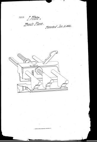
Page 1.
7951X
I. White,
Bench Plane.
Patented Jan. 9, 1834.
Page 2.
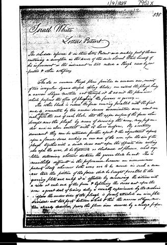
Israel White
Letters Patent
The schedule referred to in these Letters Patent and making part of these containing a description in the words of the said Israel White himself of his improvement in the instrument or tool called a Plough used by carpenters & other artificers.
The old or common Plough plane familiar in common use, consists of two irregular square shaped plough blocks; one called the plough, having a narrow oblique mortice cut through it to admit the plane iron which performs the office of ploughing the furrows or grooves.
The other block is called the fence running parallel with the first and is connected by two wooden screws denominated arms about one inch distant from the end of each block, that the upper surface of the fence when brought near the plough by means of screwing the arms, may pass under and in close contact with its lower surface. By a contrary movement they can be extended further apart & the adjustment depends upon a female screw working on one arm of the arm upon the side of the plough together with a small screw nut upon the opposite side working also upon the arm, to be tightened or slackened at pleasure, which regulation determining whatever distance the groove shall be cut. This is nevertheless difficult in the performance because an inconvenience presents itself whenever both arms are to be moved in such a manner that the position of the fence shall be brought parallel to the grooving plate and unless it is effected by measuring the distance with a rule at each end of the fence & tightening the screw nut upon the arm, a great deal of tedious delay is usually experienced by the mechanic.
Upon the under side of the plough is firmly attached an iron plate divided into two parts between which & this the narrow oblique mortice already described, passes the plane iron secured by a wedge proper.
Page 3.
7951X
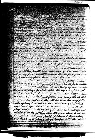
for such a purpose as the iron plate and the plane iron being considerably lower than the plough block, the former or groove is sunk into brass so as to admit ease to regulate & it is so regulated by the following contrivance: Upon the top of the plough block, a small trap plate is sunk immediately over a square mortise passing thru the plough to admit a square block of brass called a barrel to be moved up and down by means of a screw secured by a collar under which the trap plate the lower end of the screw entering & is made fast to the upper part of the barrel. The bottom of the barrel is firmly attached to a short piece of plate iron of about 3 or 4 inches long, having an extensive notch cut out of the line next to the grooving plate, extending over the divided part of that plate where the plane iron passes & as ease, or drawing with the movement of the barrel.
This notched piece of iron is denominated a shoe & when worked by the screw and barrel the whole is altogether known by the application of the stop.
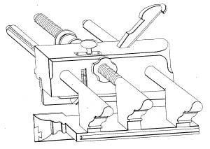
The above is the old fashioned construction of a common plough plane whose arms when moved to measure any or given distance from the fence, could never effect its parallels with the grooving plate without recourse to the rule for adjustment the screw was always found tedious and troublesome & causing much delay. It is obviated to manifest any imperfection and to keep the fence steadily in its required position when the proper distance of the groove is to be determined is the object of my improved invention upon the plough for which I claim the right to a patent it being wholly new & distinguished from any other invention heretofore known or discovered. It consists of three arms passing thru the block nearly in a line with each other, the two outer ones being plain sliding cylindric & the middle one a screw & not with female screws much upon the same construction and size as the old plough arms. By adjusting this screw arm with the nut attached to it the distance where the groove should be cut can be ascertained with great facility & precision, & the fence being kept steadily in its place is always parallel to the plate without
Page 4.
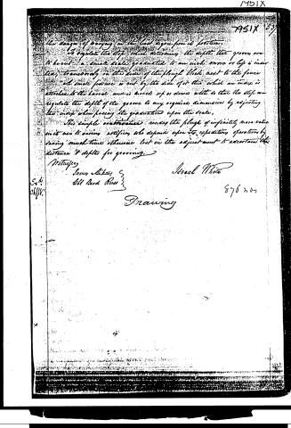
the danger of varying in the lead degree from its position.
To regulate the stop which determines the depth that grooves are to be cut—a small scale graduated to an inch more or less is inserted, transversely in the side of the plough block next to the fence. A small fixture is cut by the side of it to which an index is attached to the barrel and is moved up or down with so that the stop can regulate the depth of the groove to any required dimension by adjusting the index when passing the graduation upon the scale.
This simple contrivance renders the plough of infinitely more value in its use to various artificers who depend upon its expediting operations by saving much time otherwise lost in the adjustment to ascertain the distance & depths for grooving.
Witness
James Sikes
Old Bard Press
Isaac White
876 205
Drawing
Exh.
chfiv.
7951X 537
Published accounts: journal notice
Notice in the monthly list of patents, with remarks
Journal of the Franklin Institute, new ser., vol. 14 (1834), p. 109 · View the page
1. For a Plough Plane; Israel White, city of Philadelphia, January 9.
Remarks. In the specification of this patent considerable space is taken up by the description of the plough used by cabinet makers and joiners, as it is usually made; however, as no one will feel interested in the improvement who is not acquainted with the instrument in its present form, we omit this description altogether. For many years past it has been the practice to regulate the distance of the fence from the plough iron by means of two arms having screws and nuts on them; previously to this, the arms were made smooth, and fitted nicely into holes made in the block of the plough, where they were tightened by wedges; the plough now patented may be considered as a modification of these two modes. It has three arms, the middle one of which has a screw and nut, whilst the two outer are cylindrical, and slide easily through two holes in the block. The intention of this is, to preserve the parallelism of the fence to the plate of the plough, without the trouble of setting both ends by the rule. The stop, or slide, which regulates the depth of the groove, is formed in the usual manner, but a mortise, or slot, is made through the side of the plough on to the brass part of the slide, which has graduations upon it that indicate the depth to which it is set. Fillister's, and other planes, having similar moving parts, are to be made in the same way. The labour of making planes upon this plan is but little increased, and it manifestly facilitates the setting of them to the gauge required.
DATAMP: illustration
Illustrations from DATAMP

DATAMP (Directory of American Tool and Machinery Patents), via the Internet Archive · Archived DATAMP page
About this record
- Patentee
- DATAMP
- Date
- the Name and Date index of patents, DATAMP, USPTO records
- Invention
- DATAMP
- Listed in
- the Name and Date index of patents, DATAMP, USPTO records, Jim Shaw's X-patent list, the Journal of the Franklin Institute, Burke's List of Patents (1847)
- Burke's 1847 Patent Office list gives the same patent.