

Drawings and documents
National Archives restored drawings: drawing
Orin Ellis' Patent Drawing for a Machine for Mortising

National Archives, Restored Patent Drawings (Record Group 241) · Full-size scan at the National Archives · Catalog record
Show the text on the drawing Hide (101 words)
Words on the drawing as machine-read by the National Archives; not checked. Useful mainly for searching.
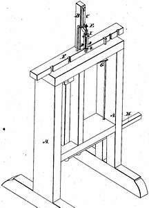
144. WOOD WORKING MACHINES. / Orin Ellis / Punching Cutters. / CLASSIFICATION / Patd / #2 / 7955X / Martioing: / NOISI AIT / Jan. 16, 1834 / atenter / 7955 X / Reference / First Perspective view. / Fige2. from f view / Figer3, stock and chisels. / Fid 4 stock separathand detarhed / parts. A forts.B. slide port / o, stock, D. chisils. E clearer, / Efence G.spring ,H, treadle, / Iband paping round the chink / K " and strap of iron / Patent office becomber yth / Made under Nhe durection of the Commisioner of Patents / conformity with the of 30d March 1837 / We Sermorth / Commissioner of I atent
USPTO scan
The patent as scanned by the USPTO
-
 Page 1
-
 Page 2
-
 Page 3
-
 Page 4


U.S. Patent and Trademark Office · Google Patents
Show the transcription Hide (1,387 words)
Machine transcription (LightOnOCR) of the pages as scanned by the USPTO, most of them the handwritten copies made when the records were restored after the 1836 fire. Not checked; it can misread handwriting, so compare it with the scan.
Page 1.
7955X
O. ELLIS.
Machine for Mortising Window Sashes.
Patented January 16, 1834.
N. PETERS, Photo-Lithographer, Washington, D. C.
Page 2.
1/16/1834 7955X
Jan. 16, 1834
Orin Ellis, of Orange, Mass.
Letter Patent 7955
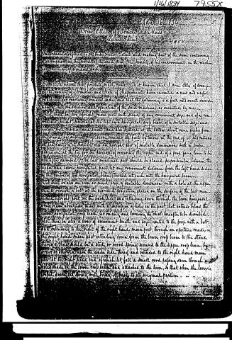
The Schedules referred to in these Letters Patent and making part of the same containing a description in the words of the said Orin Ellis himself, of his improvement, in the machine for mortising window sashes.
In order to show these presents shall come, Be it known that I Orin Ellis, of Orange, in the County of Franklin and State of Massachusetts have invented a new and useful machine for mortising window sashes, and that the following is a full and exact description of the construction and operation of the said machines as invented by me.
Let there be two upright main posts with stands, of any convenient size and of a convenient height, secured at the top by a horizontal cross beam of a suitable size and length with mortises and tenons, and also secured at the bottom about nine inches from the stands by another cross beam uniting the parts by tenons in the end of it, and mortises in the parts. Let there be also an upright post of suitable dimensions with a proper projection at the top for the purpose of receiving the upper end of a prop for a lever to be hereafter described. The last mentioned post should be placed perpendicular between the upper and lower horizontal posts, at any convenient distance from the left hand side of the centre of the horizontal beams, tenoned at each into the horizontal beams.
Let there be also an iron or wood prop of suitable dimensions with a hole at the upper end to receive a bolt at the aforesaid projection, placed on the surface of the last mentioned upright post on the back side, and extending down through the lower horizontal cross beam about six inches with a succession of holes in the part that extends below the lower horizontal cross beam for raising and lowering the chisel hereafter to be described.
Let there be also a lever of convenient length and size, united to the prop with a bolt, and extending to the right of the right hand main post, through an aperture made in the right hand main post extending down from the lower cross beam to the stand thereof. There should be a steel or wood spring secured to the upper cross beam by means of otherwise upon the under side thereof and extended to the right hand main post at the right hand end of which let fall a small cord passing down through a hole made in the lower cross beam and attached to the lever, so that when the lever is raised down the spring will bring it back to its original position.
Page 3.
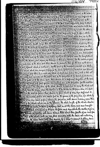
or the same effect may be produced by attaching a weight to a pulley fixed on the under side of the upper cross beam; also let there be a slide post of any convenient size sufficient to give it strength. This slide post is to pass perpendicular through the centre of each of the longitudinal cross beams, mortising being made in the said beams sufficiently large to admit the slide post and extending down through the lower cross beam and united to the lever by a tenon inserted in a loose mortise in the lever, and secured by a bolt. The slide post is also to extend up above the upper cross beam sufficiently high to affix a stock for chisels so that when the slide post is thus placed, it will move down and up by the operation of the lever. Another part of the machine is what is called a rest or fence of any suitable length, longer than the upper cross beam for the purpose of giving space to receive the piece to be mortised. There should be notches or gains made in the rest from each end of it, nearly to the slide post for the accommodation of moveable stops on each side of the slide post. The fence or rest is to be placed and secured fast on the upper side of the upper cross beam, lying on the surface upon the longitudinal centre, the sliding post passing up through it through a mortise. In the notches or gains on each side of the slide post there should be moveable stops for the ends of the piece to rest against which is mortised. Another part of the machine consists of a stock and chisels, which are designed to perform the works of mortising described and placed as follows: Set there be a cast-iron stock of about nine inches long with a hole at the upper end, and one at the upper end of the projection to be described, to receive bolts to fasten it to the slide post. There should be a sufficient projection at the lower end of the stock with four grooves, one on each side of the projection, for the insertion of the chisels. The projection of the stock should be sufficient to carry the chisels out directly over the place where the mortise is to be made in the piece when it is put against the rest or fence. There should be four chisels of any size sufficient to make the mortise, placed and made fast in the grooves of the projection of a stock by means of an iron band, passing around the projection with screws bearing upon them part of the chisels which are in the grooves. The whole length of the chisels should be five or six inches, or more if necessary, bent in at the lower ends and brought to the stock in such a manner as to give the form and size which the mortise requires, and secured by another iron band around them about three fourths of an inch from the edges of the chisels, with an iron strap connected with the band, and extending under the upper band, and then secured by a screw to prevent it sliding down.
Page 4.
1/16/1834 7955x
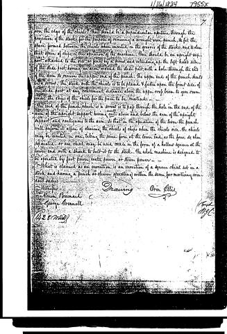
over the edges of the chisel. There should be a perpendicular aperture through the projection of the stock, for the purpose of receiving a wrought iron punch, to fit the space formed between the chisels when inserted in the grooves of the stocks, and to clear that space of chips, in the operation of the machine. There should be an upright support attached to the rail or fence by a screw, and extending up the left hand side, of the slide post, having an arm around the slide post, with a hole through the end of the arm to receive the upper end of the punch. The upper end of the punch should be a screw. The stock with the chisels is to be placed & fasten upon the front side of the slide post at any convenient distance above the upper cross beam to give room under the edges of the chisels for the piece to be mortised.
The end of the punch, which is a screw is to pass through the hole in the end of the arm of the upright support having cuts above and below the arm of the upright support, and contiguous to the arm, so that in the operation of the lever the punch will perform its office of clearing the chisels of chips when the chisels rise. The chisels may be united in one, taking the same form at the lower end, as the four do when separated, or one chisel may be used made in the form of a hollow square at the lower end with a shank to bolt it to the stock. The whole machine is designed to be operated by foot power, water power, or steam power.
What is claimed as an invention, is an invention of a square chisel set in a stock and having a punch or cleaner operating within the same, for mortising wood.
Witnesses
Almon Brainard
George Greenwell
(428 words)
Drawing
Orin Ellis
(End)
M.G.C.
Published accounts: journal notice
Notice in the monthly list of patents, with remarks
Journal of the Franklin Institute, new ser., vol. 14 (1834), p. 114 · View the page
13. For a machine for Mortising Window Sash; Orin Ellis, Orange, Franklin county, Massachusetts, January 16.
Remarks. A very imperfect description is given of this machine, although by its aid, and that of the drawing, we can form a tolerable idea of its general construction. The strips to be mortised are placed upon a suitable bench, or table, from which rises, perpendicularly, a standard, that sustains the chisel, and the pieces which are to serve as sockets, or guides, for it to slide in. A lever is fixed in the manner of a treadle, near to the lower part of the table, and the chisel is forced up and down by its aid; a pitman, or sliding rod, extending from it for that purpose. The lever is raised by means of a spring, and forced down by any adequate power. The chisel is to be made in four pieces, so bent at their lower ends that they shall, combinedly, form a socket of the size of the mortise to be made, the whole four sides of it being cut by them at once, whilst there is a punch, or clearer, so fixed as to force out the chips. "What is claimed as an invention, is, the square chisel set in a stock, and having a punch, or clearer, operating within the same, for mortising window sashes." There are several patents for mortising with chisels in the form of a square socket, but we believe they are all in one solid piece. To form such a tool of four pieces, to cut so as not to admit chips in the joining angles, will be a thing of some difficulty.
DATAMP: illustration
Illustrations from DATAMP

DATAMP (Directory of American Tool and Machinery Patents), via the Internet Archive · Archived DATAMP page
About this record
- Patentee
- DATAMP
- Date
- the Name and Date index of patents, DATAMP, USPTO records
- Invention
- DATAMP
- Listed in
- the Name and Date index of patents, DATAMP, USPTO records, Jim Shaw's X-patent list, the Journal of the Franklin Institute, Burke's List of Patents (1847)
- Burke's 1847 Patent Office list gives the same patent.