

Drawings and documents
National Archives restored drawings: drawing
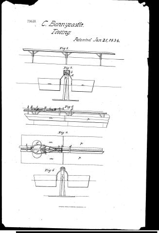
Charles Bonneycastle's Patent Drawing for an Improvement in Canals and the Application of Locomotion

National Archives, Restored Patent Drawings (Record Group 241) · Full-size scan at the National Archives · Catalog record
Show the text on the drawing Hide (58 words)
Words on the drawing as machine-read by the National Archives; not checked. Useful mainly for searching.
Cl ASS 115, -MARINE PROPULSION / TOWING / th 19 Internal Power / Dirl 22 / 115 / 115. SHIPS / 1. PROPULSION / # 79637 / 7963 / ON, / [139] Towing. / Charles Bennycastle / CLASSIFICATION / 7963 X / 1152.8 / DIV ISION. / Imp in Canals application LLoco. / motive Engines &e: / Patented 21January 1834 / Fig.2. / CLASSIFICATION / aPb / 7963x / DIV ISION. / Railways / Fig. / Fig.4. / in / ne / 777 / Tio.5
USPTO scan
The patent as scanned by the USPTO
-
 Page 1
-
 Page 2
-
 Page 3
-
 Page 4
-
 Page 5
-
 Page 6


U.S. Patent and Trademark Office · Google Patents
Show the transcription Hide (1,660 words)
Machine transcription (LightOnOCR) of the pages as scanned by the USPTO, most of them the handwritten copies made when the records were restored after the 1836 fire. Not checked; it can misread handwriting, so compare it with the scan.
Page 1.
7963X
C. Bonnycastle.
Towing.
Patented Jan. 21, 1834.
Fig. 1.
Fig. 2.
Fig. 3.
Fig. 4.
Fig. 5.
Page 2.
7963X
Jan. 21, 1834
Charles Bonnycastle of Alleghany Co Virginia
Letters Patent
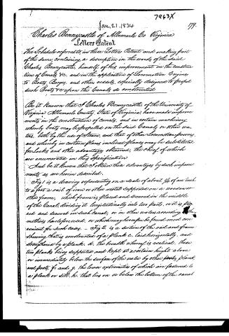
The Schedule referred to in these Letters Patent and making part of the same, containing a description in the words of the said Charles Bonnycastle, himself of his improvement in the construction of Canals &c. and in the application of Locomotive Engines to Boats, Barges, and other vessels, especially designed to propel such Boats &c upon the Canals so constructed.
Be it known that I Charles Bonnycastle, of the University of Virginia Alleghany County, State of Virginia, have made improvements in the construction of Canals, and in certain machinery whereby boats may be propelled on the said Canals or other waters, both by the use of Steam, and that of other Locomotive powers, and whereby in certain places inclined planes may be substituted for Locks and other advantages obtained, the chief of which are enumerated in this specification.
And be it known that I obtain these advantages by such improvements as are herein described.
Fig 1 is a drawing representing on a scale of about 1/4 of an inch to a foot a rail of iron or other metal supported on a wooden or other frame, which frame is placed and secured in the middle of the Canal, dividing it longitudinally into two parts, or it is placed and secured in such Canal, or in other waters according to the methods heretofore used, or which may hereafter be found most convenient for such cases. — Fig 2 is a section of the rail and frame showing that it is constructed of a plank c, laid horizontally, and strengthened by a plank d, the breadth whereof is vertical, these two planks being supported and kept at a certain height above or immediately below the surface of the water by other planks, plank and posts, f and g, the lower extremities of which are fastened to a plank or sill, h, that lies on or below the bottom of the canal.
Page 3.
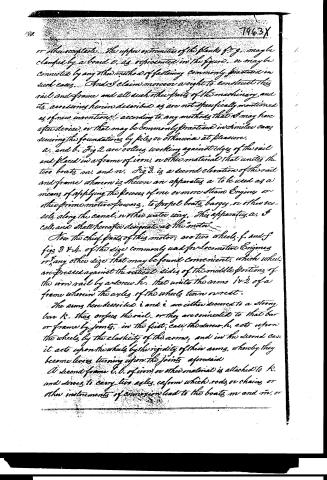
or otherwise. The upper extremities of the planks f, g, may be clamped by a board v, as represented in the figure, or may be connected by any other method of fastening commonly practiced in such cases. And I claim moreover a right to construct this rail and frame and all such other parts of the machinery and its accessories herein described as are not specifically mentioned as of new invention, according to any methods that I may hereafter devise, or that may be commonly practiced in similar cases securing the foundations by piles or otherwise at pleasure.
a. and b. Fig 2 are rollers working against edges of the rail and placed in a frame of iron, or other material that unites the two boats m. and n. Fig 3 is a second elevation of the rail and frame whereon is shown an apparatus a. to be used as a means of applying the powers of one or more steam engines or other prime motive powers, to propel boats, barges, or other vessels along the canal, or other water way. This apparatus a. I call and shall hereafter designate as the "motor".
Now the chief parts of this motor, are two wheels f. and f figs 3 & 4. of the size commonly used for locomotive engines or any other size that may be found convenient, which wheels are pressed against the vertical sides of the middle portions of the iron rail by a screw h. that unites the arms i & i of a frame wherein the axles of the wheels turn overcast.
The arms here described i and i are either secured to a strong bar k. that crosses the rail, or they are connected to that bar or frame by joints, in the first case the screw h. acts upon the wheels by the elasticity of the arms, and in the second case it acts upon the wheels by the rigidity of their arms, whereby they become levers turning upon the joints aforesaid.
A second frame l. l. of iron, or other material is attached to k. and serves to carry two axles, cefrom which rods, or chains, or other instruments of connexion lead to the boats m and m, or
Page 4.
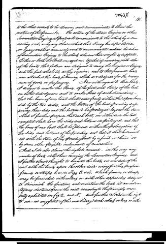
to the three vessels to be drawn, and communicate to them the motion of the frame k. The action of the steam Engines or other Locomotive Engines, I propose to communicate to the wheels by a connecting rod, or by any other method that I may hereafter devise, or by any method commonly used to communicate motion the action of Locomotive Engines to the wheels, when on their weight is supported. Either or both the Boats m, and m, together if necessary, with other of the boats that follow are designed to carry the Engine or Engines and the fuel which it, or they require, and to their foremost boats are attached the boats following which are designed for the conveyance of goods or passengers. Now with regard to these boats, I design to make the Bows of the first, and stems of the last on either side square, and to make them of such dimensions—that the bow of one boat shall enter freely within the space bounded by the two sides, and the bottom of the boat preceding supposing their sides and the bottom to be prolonged beyond the stem. And I further propose that each boat, on either side the last excepted shall have the sides and bottom so prolonged, and that the bows of one boat shall be placed within the prolongation of the sides and bottom of the preceding and that it shall be connected with the stem of the preceding boat by a joint or chain or by some other flexible instrument of connection. And I do also claim the right to connect—in this way any number of boats with those carrying the Locomotive Engines, and I further claim the right to connect the boats on one side of the rail with the boats upon the other side using for this purpose frames or straps b, c, a, v. Figs 3. & 4. which frames or straps may be furnished with rollers or with other apparatus designed to diminish the friction, and maintain the boats at an advantageous distance from the rail, according to the principle more fully exhibited in fig 2. and 5. And further I claim the right to use in any part of the machinery such wheels, rollers or other
Page 5.
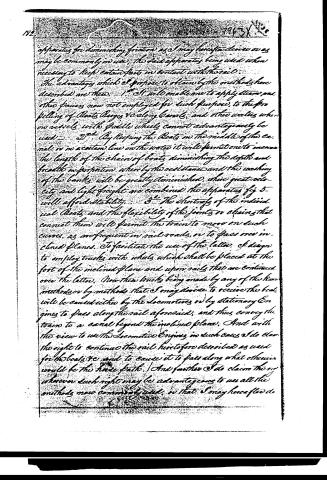
apparatus for diminishing friction as I may hereafter devise or as may be commonly in use, the said apparatus being used when necessary to keep certain parts in contact with the rail.
The advantages which I propose to obtain by the methods here described are these. 1st It will enable me to apply steam and other powers now not employed for such purpose, to the propelling of Boats, Barges &c along canals, and other waters where on vessels with paddle wheels cannot advantageously be used. 2nd By keeping the Boats in the middle of the canal or in a certain line on the water it will permit one to increase the length of the chain of boats diminishing the depth and breadth in proportion whereby the resistance and the washing of the banks will be greatly diminished, where great velocity and light freight are combined the apparatus fig 5 will afford stability. 3rd The shortness of the individual Boats and the flexibility of the joints or chains that connect them will permit the train to move on such curves as are frequent in rail roads, or to pass over inclined planes. To facilitate the use of the latter, I design to employ trucks with wheels which shall be placed at the foot of the inclined plane and upon rails that are continued over the latter. Now these trucks being made by any of the known methods or by methods that I may devise to receive the boat will be caused either by the locomotives or by stationary Engines to pass along the rail aforesaid, and thus convey the train to a canal beyond the inclined plane. And with the view to use the locomotive Engines in such cases I do claim the right to continue the rail heretofore described as used for the boats &c and to cause it to pass along what otherwise would be the hard path. And further I do claim the right wherever such right may be advantageous to use all the methods now commonly used, so that I may hereafter de
Page 6.
7963X 183.
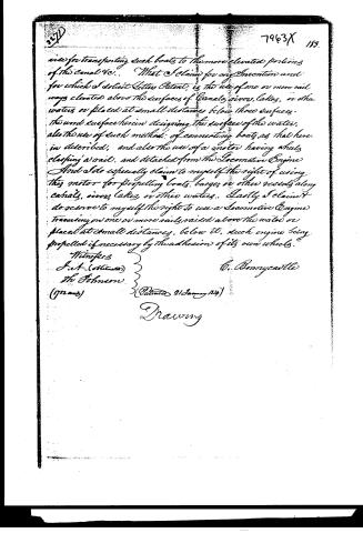
use for transporting such boats to the more elevated portions of the canal &c.. What I claim for my Invention and for which I solicit Letters Patent, is the use of one or more rail ways elevated above the surfaces of Canals, rivers, lakes, or other waters or placed at small distances below those surfaces. the word surface herein designating the surface of the water, also the use of such methods of connecting boats as that herein described, and also the use of a motor having wheels clasping a rail, and detached from the Locomotive Engine And I do especially claim to myself the right of using this motor for propelling boats, barges or other vessels along canals, rivers, lakes, or other waters.. Lastly I claim it do reserve to myself the right to use a Locomotive Engine traversing on one or more rails raised above the water or placed at small distances, below it, such engine being propelled if necessary by the adhesion of its own wheels.
Witnesses
J. A. (oblit.)
Th. Johnson.
(1732 mds)
C. Bannycastle
(Patented 21 January 1834)
Drawing
Published accounts: journal notice
Notice in the monthly list of patents, with remarks
Journal of the Franklin Institute, new ser., vol. 14 (1834), p. 118 · View the page
21. For an improvement in the Construction of Canals, and in certain machinery whereby boats may be propelled on the said canals, or on other waters, &c; Charles Bonnycastle, University, Albemarle county, Virginia, January 21.
Remarks. This improvement in canals relates entirely to the constructing within them an apparatus to be connected with some motive power, usually a steam engine, by which boats may be propelled thereon. A rail, resembling Palmer's single rail for rail-roads, is to be constructed along the middle of the canal; it may be even with, or elevated to any convenient height above, the surface of the water. This rail is to be surmounted by one of iron, which is to be acted upon by the power employed to propel the boats. These boats are intended to be long and narrow, as they are to go two abreast, one on each side of the rail; a train of them is to be connected together, the two foremost of them carrying the steam engine, or other motor. Two wheels, which may be of the size usually employed upon railroads, are made to revolve horizontally against the opposite sides of the rail, embracing it between them, they, by a suitable contrivance, being made to press against it, so that by their friction the locomotion may be effected. The boats on the opposite sides of the rail, are to be connected together by suitable straps which pass over it, and their stems and sterns are so constructed and adapted to each other, that whilst they are allowed to have play enough to turn round curves, they may operate, as nearly as possible, like one continuous boat. The advantages anticipated from the foregoing construction are the following. 1st. The application of steam, or other power, for propelling boats upon canals, or other waters, where it is not now employed, because the action of paddle wheels would be destructive to the banks. 2nd. The keeping in a certain line, by means of the rail, admitting of a great increase in the length of the chain, or train, of boats; their width and depth being diminished in proportion, whereby the resistance, and the consequent washing of the canal, are greatly decreased. 3d. The using of short boats, whereby a long chain of them will be enabled to turn on such curves as are common on canals; and also to allow them to pass over inclined planes. In passing over inclined planes, wheels, with trucks, such as are now employed, or others which may be found convenient, are to be used, locomotive or fixed engines being employed. The claim is in the following words:"What I claim as my invention, and for which I solicit letters patent, is the use of one or more rail-ways elevated above the surfaces of canals, rivers, lakes, or other waters, or placed at small distances below those surfaces; the word surface herein designating the surface of the water. Also, the use of such method of connecting boats as that herein described. And, also, the use of a motor, having wheels clasping a rail, and detached from the locomotive engine. And I do especially claim to myself the right of using this motion for propelling boats, barges, or other vessels, along canals, rivers, lakes, or other waters. I claim, and do reserve to myself, the right to use a locomotive engine, traversing on one or more rails raised above the water, or placed at small distances below it; such engine being propelled, if necessary, by the adhesion of its own wheels." Various contrivances have been made for applying the motive power on board of steam-boats otherwise than by paddle wheels; as, for example, by a chain, or rope, along the canal; by wheels acting upon the bottom, or upon the tow path, and by logs lying along the middle, having racks upon them, into which a toothed wheel might work; the present plan we believe to be new, and the main, if not the only difficulty in the way of its adoption, is that the canal and boats must be constructed exclusively with a view to it.
About this record
- Patentee
- DATAMP
- Date
- the Name and Date index of patents, DATAMP, USPTO records
- Invention
- DATAMP
- Listed in
- the Name and Date index of patents, DATAMP, USPTO records, Jim Shaw's X-patent list, the Journal of the Franklin Institute, Burke's List of Patents (1847)
- Burke's 1847 Patent Office list gives the same patent.