

Drawings and documents
National Archives restored drawings: drawing
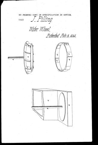
J. Pilling's Patent Drawing for a Horizontal Sunk-curb Waterwheel

National Archives, Restored Patent Drawings (Record Group 241) · Full-size scan at the National Archives · Catalog record
Show the text on the drawing Hide (73 words)
Words on the drawing as machine-read by the National Archives; not checked. Useful mainly for searching.
188. HYDRAHL in / $150 / Turbins / Side-Ring go / J o PILLING / classification / 7992 X / Horizontal Sunk-curb WaterWheel / DIVISION. / Patented 3-Feb 1834 / A Shoft / B. / Culinder / C. / Flanch / Buckets / Curb / F. / Curved win? and Intets / Box. / F4 / P. / Patent office March 29"18"9 1839 / G. Strickland Del / Made under the clisection of the commisions of naturts / in conformity with ach 3a Yarch 1837- / Swooth
USPTO scan
The patent as scanned by the USPTO
-
 Page 1
-
 Page 2
-
 Page 3


U.S. Patent and Trademark Office · Google Patents
Show the transcription Hide (818 words)
Machine transcription (LightOnOCR) of the pages as scanned by the USPTO, most of them the handwritten copies made when the records were restored after the 1836 fire. Not checked; it can misread handwriting, so compare it with the scan.
Page 1.
NO PRINTED COPY OF SPECIFICATION IN OFFICE.
7992X
J. Pilling,
Water Wheel,
Patented Feb. 3, 1834.
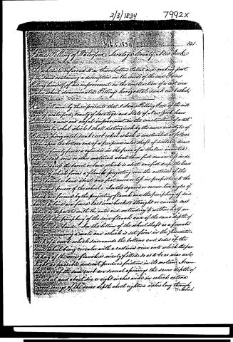
Page 2.
2/3/1834 7992X
Feb. 5, 1834 141.
James Pilling of Waterford, Saratoga County, New York
The schedule referred to in these Letters Patent and making part of the same containing a description in the words of the said James Pilling himself of his improvement in the construction of a cast iron water wheel denominated Pilling’s horizontal sunk curb wheel.
Know all men by these presents that I James Pilling Son of the village of Waterford, County of Saratoga and State of New York have invented a new and useful improvement in the construction of a cast iron water wheel which I shall distinguish by the name and style of Pilling’s horizontal sunk curb wheel which is constituted as follows.
Near the bottom end of a perpendicular shaft of suitable dimensions is firmly fixed a cylinder in the form of a shallow inverted cup of cast iron or other materials about three feet more or less in diameter across the barrel or band which is about one foot deep the head or cup of which forms a flange projecting over the outside of the said barrel or band about one foot more or less in proportion to the intended power of the wheel. In the square or corner two angles of which are formed by the projecting flange and the periphery of said barrel or band are fixed cast iron buckets straight or curved cast iron or separate with the outer end extending it within half an inch of the periphery of the said flange and of the same depth of the barrel or band. In the bottom of the wheel shaft is a female socket receiving a male one which is set firm in the formation work of a curb which surrounds the bottom and sides of the said wheel being circular with a cast iron rim into which the periphery of the said flange is nicely fitted so as to be as near water tight as possible and not produce friction in its motion. Around the sides of the said curb are several openings the same depth of the wheel and about six or eight inches wide in which extend curved rows of the same depth about eighteen inches long through which
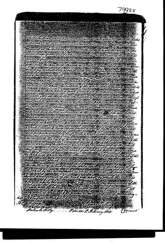
Page 3.
which the head water passes on a tangent having only so wide a take of the wheel at intermediate distances between the head gates and openings in the bottoms of the cistern through which the water passes into its orifice from the buckets, or may in the nature of the cistern be made a firm reservoir either from an open well which the water passes from the penstock through said inlet, or from the buckets of from one long water wheel by a pair of stops which close the channel in the cistern on one side of its entrance from the penstock, it passes round in an opposite direction, and enters the cistern through said inlet in a curved line, after the buckets of the wheel have been set up to its force upon the buckets a short time back and falls down the wheel or water gate in the bottom in a rotary lock of its entrance through said inlet, and the bottom of the water pipes in and discharges at the next bottom opening. The outside box or cistern may be made of plank and bolts or iron with the rims at the top and bottom, the sides made of staves or otherwise, or may be made of iron, cast wheels or in parts. The penstock gate may be the ordinary gate or a wheel made to turn upon center bearing by means of a socket and perpendicular key shaft with a crank lever upon its upper end. Underneath the cistern of receiving a tongue may be fixed to carry the waste water any direction required. The upper end of the wheel shaft may run in bearings as usual from which power may be received by coupling wheels, bands or otherwise. That portion or part of this improvement which claims any new or novel invention is just. The method of introducing the water upon a discharge from the wheel by its arrangement is above described, and thereby the combined arrangement of the cistern and wheel by which the latter is being raised by the water that is drawn upon the under side of the flench and the bottom supported from the friction without any waste of water, is of great or extra expense of machinery.
4th. Water for 23rd September 1833
S. J. H. H. H.
John S. Kelly.
Patented 3, February 1834
(771 and)
Published accounts: journal notice
Notice in the monthly list of patents, with remarks
Journal of the Franklin Institute, new ser., vol. 14 (1834), p. 172 · View the page
1. For a Water Wheel, denominated the "Horizontal Sunk Curb Wheel;" James Pilling, jr., Waterford, Saratoga county, New York, February 3.
Remarks. This is to be a horizontal wheel with a vertical shaft passing up through a penstock. The cylindrical part of the wheel may be three feet in diameter, and a foot in depth; this is to be surrounded by wings, or buckets, either straight or curved, the cap or top plate of the wheel forming a circular cover, or flanch, which extends about half an inch beyond the extreme edges of the buckets. This wheel is to be let into a circular curb of wood, or of iron, which is to fit nicely, the projecting flanch forming a joint as nearly as may be water tight. The water is to be let on to the wheel, tangentially, through three or four openings in the surrounding curb, a circular channel being provided for that purpose, and each opening being furnished with a wing in the channel, to give the water a proper direction. The water, after acting upon the buckets, is to escape through openings in the bottom of the curb. The head of water acting upon the flanch, or horizontal rim, which forms the cover of the buckets, presses it upwards, and prevents all undue friction upon its centre. The claim is to "the method of introducing the water upon, and discharging it from, the wheel, by the arrangement as above described. The combined arrangement of the curb and wheel, by which the latter is buoyed up by the water in its action upon the under side of the flanch, and the bottom step relieved from the friction, without any waste of water, loss of power, or extra expense of machinery." This resembles other wheels for which patents have been obtained, although we are not aware that its exact likeness is to be found upon the files of the patent office. The mode of letting on the water, however, is not new, and the principle of sustaining the weight of the shaft and its appendages by the upward pressure of the water, has been repeatedly applied and variously modified.
About this record
- Patentee
- DATAMP
- Date
- the Name and Date index of patents, DATAMP, USPTO records
- Invention
- DATAMP
- Listed in
- the Name and Date index of patents, DATAMP, USPTO records, Jim Shaw's X-patent list, the Journal of the Franklin Institute, Burke's List of Patents (1847)
- Burke's 1847 Patent Office list gives the same patent.