

Drawings and documents
National Archives restored drawings: drawing
J. Treadwell's Patent Drawing for a Belted Roving Machine


National Archives, Restored Patent Drawings (Record Group 241) · Full-size scan at the National Archives · Catalog record
Show the text on the drawing Hide (91 words)
Words on the drawing as machine-read by the National Archives; not checked. Useful mainly for searching.
Sheet 1. 18. SPINNING / Hemp, Flax & Hair / (3Sheets) sheet / LASSINCATION / 1995-X X / D. Treadwell / DIVISION. / Belted Roving Machine / Patented Feb. 3d 1834 / 26 / 72 / 305 / TU / as / 22 / 12 / 12 / Far / Fig. 1 / FAL / DO / XXXXXXXXXXXXXXXXXXXXXXXXX
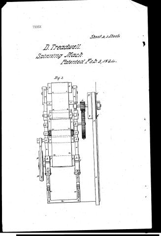
Sheet 2. 118. SPINNING / Hemp, Flax & Hair. / Sheet 2 / D. Treadwell / CLASSITICATIVELED / Roving Machine / 7995 TON. / Patented Feb. 3ᵈ 1834 / Fig. 2 / q' / 22 / 2° / 212 / 222 / 112 / /2
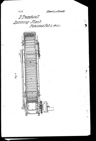
Sheet 3. 118. SPINNING, / Hemp, Flax & Hair. / $ 3 Sheet s9 sheet3 / D. Tredwell / CLASSIFICATION / Belted Roving Machine / 7995.X / Patented Feb. 3ᵈ 1834 / 26 / HE / 7/ / or / ON / ON / ON / La / Fig. 3 / Is / O D O / ON / to
USPTO scan
The patent as scanned by the USPTO
-
 Page 1
-
 Page 2
-
 Page 3
-
 Page 4
-
 Page 5
-
 Page 6
-
 Page 7
-
 Page 8


U.S. Patent and Trademark Office · Google Patents
Show the transcription Hide (1,918 words)
Machine transcription (LightOnOCR) of the pages as scanned by the USPTO, most of them the handwritten copies made when the records were restored after the 1836 fire. Not checked; it can misread handwriting, so compare it with the scan.
Page 1.
7995X
Sheet 1, 3 Sheets
D. Treadwell.
Spinning Mach.
Patented Feb. 3, 1834.
Fig. 1
Page 2.
7995X
Sheet 2, 3 Sheets
D. Treadwell.
Spinning Mach.
Patented Feb. 3, 1834.
Fig. 2

Page 3.
7995X
Sheet 3, 3 Sheets.
D. Treadwell.
Spinning Mach.
Patented Feb. 3, 1834.
Fig. 3.
Page 4.
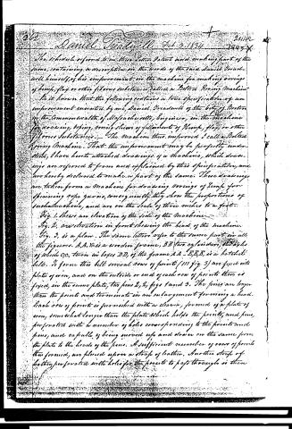
The schedule referred to in this Letter Patent and making part of the same, containing a description in the words of the said Daniel Broadwell himself of his improvement in the machine for making coverings of hemp, flax or other fibrous substances, called a "Belted Roaring Machine."
Be it known that the following contains a true specification of an improvement invented by me, Daniel Broadwell of the city of Boston in the Commonwealth of Massachusetts, Engineer, in the machine for drawing, drying, roving slivers of filaments of Hemp, flax, or other fibrous substances. The machine thus improved I call a Belted Roaring Machine. That the improvement may be perfectly understood, I have hereto attached drawings of a machine, which drawings are referred to from and explained by this specification, and are hereby declared to make a part of the same. These drawings are taken from a machine for drawing coverings of Hemp for spinning rope yarns, consequently they show the proportions of such machine, and are on the scale of three inches to a foot.
Fig. 1. Shews an elevation of the side of the machine.
Fig. 2. an elevation in front shewing the head of the machine.
Fig. 3. is a plan. The same letters refer to the same part in all the figures. A, A, &c. is a wooden frame, B B two cylinders, the axles of which C C, turn in boxes D D, of the frame A A. E, E, E, is a hatched belt. It forms this belt several rows of points (III fig. 3) are fixed into plates of iron, and on the outside or end of each row of points there is fixed, in the same plate, two pins 2, 2, figs 1 and 3. The pins are longer than the points and terminate in an enlargement forming a head. Each row of points is furnished with a cleaner, formed of a plate of iron, somewhat longer than the plate which holds the points, and pins, perforated with a number of holes corresponding to the points and pins, and capable of being moved up and down on the same from the plate to the heads of the pins. A sufficient number of rows of points thus formed, are placed upon a strip of leather. Another strip of leather, perforated with holes for the points to pass through is then
Page 5.
passed under the cleaners and passed down upon the plates, the points passing through the holes. The two strips are then riveted together, having the plates between them. The strips thus united are then passed around the cylinders B, B, and having their ends properly secured together, constitute with the plates, pins &c. the hatched belt, as seen at E, E, E. The rails E, E, support the cleaners, the projecting ends of which rest upon the rails, while a ledge on the inside of each rail supports the ends of the plates to which the points are fixed. It will be seen that the ends of the rails, nearest to the head of the machine, hereafter to be described, are formed into a curve having a longer radius, than that of the cylinder B, so that as the top of the hatched belt, advances towards the head of the machine, the cleaners in passing over this curved part of the rails, are raised from the leather belt, which is in contact with the cylinder, to the top of the pins.
G, G, are two iron plates, called forcing plates, which carry the cleaners from the top of the pins towards the leather belt as they pass successively by them, when carried from the bottom to the top of the left hand cylinder. H, H, is the bobbin belt, formed of a number of small wooden cylinders, fixed at their ends to two belts of leather. The bobbin belt passes over the pulleys I, I, the axles and bearings of which are distinctly seen in the drawings. The hatched belt, bobbin belt, rails, forcing plates, and connections, resemble in their form and construction an apparatus already patented, and in use, and are hereby declared to form no part of the invention for which a patent is now claimed. J, J, is a gear wheel on the shaft of the cylinder B. K, is a pinion driving the same. L, is a gear wheel on the shaft of K. M, is a pinion driving the wheel L. N, is a pulley on the shaft of M. The several shafts of these wheels and pinions are in boxes on the frame A, A, as seen in the drawings.
The head of the machine is seen at the several figures in its proper position. a, a, a, a, are two cast iron posts, to which are fixed the boxes b, b, b, holding the three rollers or pulleys, c, d, and e, f, f, are boxes, holding the pulley g. The boxes f, f, are fixed in
Page 6.
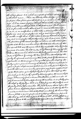
the sliding frames k, k, which are capable of sliding up and down on the posts a, a, a. There are likewise, three pulleys i, j, k, hanging in proper boxes fixed upon the posts a, a, a, as seen in the drawings. l, l, are screws passing through studs on the sliding frames k, k, and likewise through studs on the posts a, a, a. Each screw l, l, is furnished with a thumb nut, as seen in the drawings. m, m, m, is an endless band or belt, called a drawing belt, which passes over and encircles pulleys c, e, and g, and none other. n, n, is another endless band or belt, called a drawing belt which passes over and encircles the pulleys d, i, j, and k, and none other. The positions of the several pulleys, as shown in the drawings, together with the lines marked out for the belts, will show clearly the line of each belt and the course which they must take when the pulleys are made to revolve. The belt m, m, is tightened by turning up the thumb nuts on the screws l, l, which draw the pulley g, downwards. The belt n, n, is tightened by raising the boxes which bear the shaft of the pulley k, upwards and securing them to the posts by the screws, as represented in the drawings. o, is a cog wheel, upon the shaft of the pulley e, p, is a pinion running in the wheel o. The pinion p, is fixed upon a proper shaft one end of which runs in a box fixed to the post a, and the other end runs in a box fixed upon any proper support set up for the purpose. q, is a tight pulley fixed upon the shaft of the pinion p, q, is a loose pulley capable of turning upon the same shaft. r, is a belt running from a drum below the floor, or wherever else it may be convenient to place it, for driving the machine. s, is a pulley upon the shaft of the pulley e. t, t, t, is a belt passing over the pulley s, and the pulley k, here before described. The posts a, a, a, stand upon the floor and are kept at a proper distance from each other by the bars u and v, and are connected with the frame A, B, by the connecting bars or plates w and x. y represents a plate of sheet iron fixed to the stand y, which stand is fixed to the rail B B. A like plate and stand is fixed to the one opposite the opposite side to that seen at right.
Page 7.
The object of these plates is to direct the hemp, as will be hereafter described, to the drawing belts m and n.
Let us now suppose, the belt r, running in the direction of the arrows, to be passed upon the tight pulley q. This will give motion to the several wheels, pulleys and belts, in such directions and with such velocities as must be due to their relative sizes and connections, which have been before described, or may be seen and measured by the drawings. Now suppose a quantity of hemp forming a column, or large moving, to be placed in a trough, or upon a board, so that its end shall be conducted to the hatchel belt. This will be forced into and pierced by the points of that belt by the action of the bibbin belt and runs along with that belt until its end arrives at the plates 33. These plates direct it to the place where the belt m, meets the belt n, on the upper side of the pulley e and beneath the pulley d. Now the tension of the belt m, being very great, this nips or forces the fibres of hemp very closely upon the belt m, passing round the pulley d, and they are carried in the space between the two belts, and on the outside of both, in the direction which those belts pass, until they are delivered where the belts separate from each other, above the pulley c, and under the pulley j. It will be understood that the hemp is nipped and carried along wholly by the tension of the belts and that the distance from the periphery of one pulley to the periphery of another pulley, is always greater than the thickness of both belts together with the thickness of the fibres of hemp forming the moving. The drawing belts move much faster than the hatchel belt, as will be seen by the sizes and connections of the parts concerned in producing the motions. Therefore the fibres of hemp must be drawn through the points of the hatchel belt and the column of hemp which lay in the hatchel belt must be reduced in size to a degree corresponding with the greater velocity of the drawing belts than that of the hatchel belt. So the hemp may be continually
Page 8.
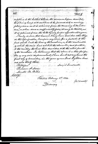
266. 7995X
supplied to the hatchel belts in the manner before described, the fibres of hemp will continue to be formed into a roving, falling down as it is delivered from the drawing belts, into a can, or when drawn sufficiently fine, it may be twisted, as it is delivered from the belts by any proper apparatus into a yarn.
I hereby declare, that however I may have described other things in this specification, I confine my claim for a patent, to the part which I call the head of the machine, or, to the combination of which the said head exhibits the character; and further, to the uniting the head thus described, with the other parts of the machine. In testimony that the above is a true specification of my said improvement, I have here to set my hand this first day of November, in the year of our Lord eighteen hundred and thirty-three.
Witnesses
Daniel Broadwell
Theodore A. Dunn
Horatio M. Willis
Patented February 3rd, 1834. (2130 words)
Drawing
Published accounts: journal notice
Notice in the monthly list of patents, with remarks
Journal of the Franklin Institute, new ser., vol. 14 (1834), p. 173 · View the page
4. For an improvement in a machine for Making Rovings of Hemp, Flax, or other fibrous substances; Daniel Treadwell, Engineer, Boston, Massachusetts, February 3.
Remarks. This patent is taken for a drawing head, to be used in drawing out the fibres of hemp and flax; it may be appended to the machinery carrying the hatchel and bobbin belts, formerly patented by Mr. Treadwell, or it may be added to other machinery for a like purpose. Were we to attempt to describe it without a drawing, we should not probably, succeed in giving an adequate idea of its construction, and shall therefore pass it over at present without further notice than to observe, that it appears to be well adapted to effect the important and difficult purpose for which it is designed.
About this record
- Patentee
- DATAMP
- Date
- the Name and Date index of patents, DATAMP, USPTO records
- Invention
- DATAMP
- Listed in
- the Name and Date index of patents, DATAMP, USPTO records, Jim Shaw's X-patent list, the Journal of the Franklin Institute, Burke's List of Patents (1847)
- Burke's 1847 Patent Office list gives the same patent.