

Drawings and documents
USPTO scan
The patent as scanned by the USPTO
-
 Page 1
-
 Page 2
-
 Page 3
-
 Page 4


U.S. Patent and Trademark Office · Google Patents
Show the transcription Hide (1,028 words)
Machine transcription (LightOnOCR) of the pages as scanned by the USPTO, most of them the handwritten copies made when the records were restored after the 1836 fire. Not checked; it can misread handwriting, so compare it with the scan.
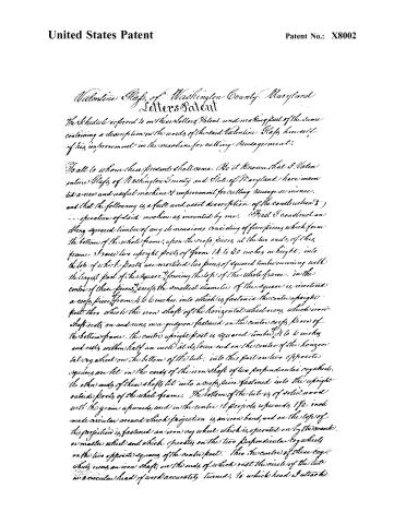
Page 2.
United States Patent
Patent No.: X8002
Valentine Glaps of Washington County, Maryland
Letters Patent
The Schedule referred to in these Letters Patent and making part of the same containing a description in the words of the said Valentine Glaps himself of his improvement in the machine for cutting sausage meat.
To all to whom these presents shall come. Be it known that I, Valentine Glaps of Washington County and State of Maryland have invented a new and useful machine & improvement for cutting sausage or mince, and that the following is a full and exact description of the construction & operation of said machine as invented by me.
First I construct an elongated squared timber of any dimensions consisting of five pieces which form the bottom of the whole frame, upon the cross pieces at the two ends of this frame I raise two upright posts of from 14 to 20 inches in height, into the top of which posts are mortised two pieces of squared timber running with the longest part of the square, forming the top of the whole frame. In the centre of these pieces, across the smallest diameter of the square is mortised a cross piece from 4 to 6 inches, into which is fastened the centre upright post, then which the iron shaft of the horizontal wheel runs, which iron shaft rests on and runs in a guigeon fastened on the centre cross piece of the bottom frame. The centre upright post is squared timber 4 to 6 inches and rests within half an inch at its lower end on the centre of the horizontal cog wheel on the bottom of the tub. Into this part on two opposite squares are let in the ends of the iron shaft of two perpendicular cog wheels, the other ends of these shafts let into a cross piece fastened into the upright outside posts of the whole frame. The bottom of the tub is of solid wood with the grain upwards, and in the centre it projects upwards 1½ inch made circular around which projection is an iron band and on the top of this projection is fastened an iron cog wheel, which is operated on by the crank or master wheel and which operates on the two perpendicular cog wheels on the two opposite squares of the centre post. Into the centre of these cog wheels runs an iron shaft, on the ends of which rest the circle of the tub in a circular head of wood accurately turned, to which head I attach
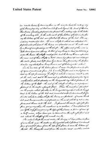
Page 3.
United States Patent
Patent No.: X8002
two circular knives, by securing them on the circular head, the cutting edge of the knives projecting at least one half inch beyond the head of the iron. These knives, operating perpendicular, present their cutting edge to the bottom of the revolving tub; to the outer circle of this bottom of solid timber forming the bottom of the tub are attached the staves of the tub. Like an ordinary constructed tub, the iron shafts to which are attached the perpendicular wheels and the knives are operated on at the outer end by a piece of iron pressing on the shaft. The upper end of this iron is kept down by an iron spring, so that if any bones or hard substances get under the knives, the shafts must yield, and the knives thrown upwards, the inner end of these shafts is kept down by a piece of iron sliding on the center posts, and kept down by a screw thus preventing the perpendicular cog wheels from being thrown out of the horizontal wheel.
On the one side of the bottom frame I raise two perpendicular pieces of squared wood made from 7 to 8 inches in height and a cross piece mounted on the top for receiving the shaft to which a common crank is attached at the outer end and to the inner end is attached a perpendicular cog or master wheel, which operates on the horizontal cog wheel fastened to the bottom of the tub. The end of the shaft working in a guide on fastened to the center upright post. When the crank is operated on the master wheel operates on the horizontal cog wheel which being fastened to the bottom of the tub and connected with the two small perpendicular wheels on whose shafts the knives are fastened, of course the tub and knives revolve and operate on the meat which is cut in small pieces and thrown into the tub. To prevent the center upright post from giving way when the machine is in motion, I have fastened to one of the cross pieces forming the top of the frame a piece of iron of a half moon, whose loose end is secured on the upright post and into which the shaft of the crank works.
In order to keep the meat under the knives I have placed a piece of iron hook near the center or horizontal wheel fastened to a small piece of wood let down from the top of the frame to near the bottom of the tub. This throws the meat from the center and into the wood.
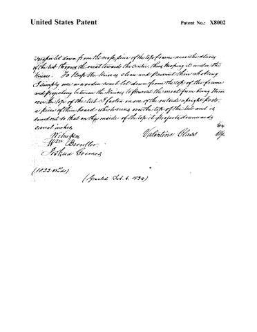
Page 4.
United States Patent
Patent No.: X8002
I simply let down from the cross piece of the top frame near the sides of the tub throwing the meat towards the centre, thus keeping it under the knives. To keep the knives clean and prevent their chocking I simply use an wooden comb let down from the top of the frame and projecting between the knives to prevent the meat from being thrown over the top of the tub & fasten on one of the outside upright posts, a piece of thin board which covers over the top of the tub and is sawed out so that on the inside of the top it projects downwards several inches.
Witness,
Wm. Brenller.
Joshua Grimes
Valentine Glass
(1022 Words)
(Granted Oct. 6, 1874)
Published accounts: journal notice
Notice in the monthly list of patents, with remarks
Journal of the Franklin Institute, new ser., vol. 14 (1834), p. 176 · View the page
12. For a Machine for Cutting Sausage Meat; Valentine Glass, Funk's Town, Washington county, Maryland, February 6.
Remarks. The meat is to be placed in a circular trough, which is made to revolve horizontally within a suitable frame. A bevelled cog wheel, turned by a crank, gears into a similar wheel which lies horizontally on a cylindrical bed, that forms the centre of the trough. Circular knives, placed upon horizontal shafts, revolve within the trough, their edges bearing against the bottom; the shafts are driven by small wheels which gear into the horizontal wheel before mentioned. There are scrapers fixed for cleaning the knives, and the sides of the trough, as they revolve, and contrivances for throwing the meat under the knives. The whole apparatus is described and figured; no part, however, is claimed, either in its individual character, or general arrangement.
About this record
- Patentee
- DATAMP
- Date
- DATAMP, USPTO records, Burke's List of Patents (1847)
- Invention
- DATAMP
- Listed in
- the Name and Date index of patents, DATAMP, USPTO records, Jim Shaw's X-patent list, the Journal of the Franklin Institute, Burke's List of Patents (1847)
- The sources give different dates; the date shown is the one most of them agree on.
- The Franklin Institute's journal confirms the date shown.
- Burke's 1847 Patent Office list gives the same patent.