

Drawings and documents
National Archives restored drawings: drawing
Walter Hunt's Patent Drawing for a Globe Stove


National Archives, Restored Patent Drawings (Record Group 241) · Full-size scan at the National Archives · Catalog record
Show the text on the drawing Hide (124 words)
Words on the drawing as machine-read by the National Archives; not checked. Useful mainly for searching.
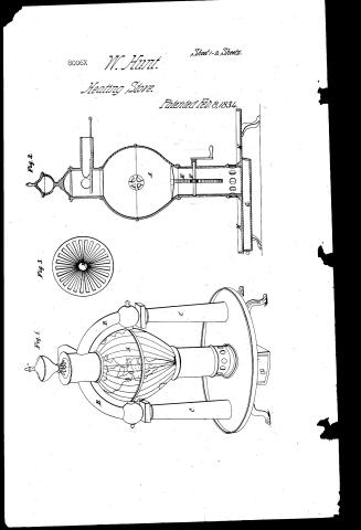
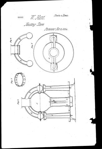
Sheet 1. 126. STOVES & FURNACES / bal Stones $600 / [154] Heating Stoves. / Hatter Hunt, / Vollapi77 / Calonfic / Globe Stove, / Patented 8th yeb 1834 / CLASSIVICATION / 8006 X / DIV ISION. / Fig1 / Fid.2. / Fif.3. / References, / Fight. from t view of stove, Fid.2. virtical section, / Fife3, top of grate. Fif.4. Section through Globe pillan / Fign5, top view, Fif. b. arch piece. Fif7 ring damper / A, lobe. B. Arch piece. C.pillars. D. grate, / E.rack for Elevating grate Efinion. / G. ashpan. H, hearth, / 02 / Patent Office Decem bor% 1641 / Made under the Correction of the Commufer over of / Patents in Conformity with the act of 3 of Mar: 1837 / 111 Eltworth / Commisines of Patents.
Sheet 2. pil. / CLASSIFICATION / 8006-X / DIVISION. / Fif4 / Fid.5 / Fif 6 / Fiig.7. / colo
USPTO scan
The patent as scanned by the USPTO
-
 Page 1
-
 Page 2
-
 Page 3
-
 Page 4
-
 Page 5
-
 Page 6
-
 Page 7
-
 Page 8
-
 Page 9
-
 Page 10


U.S. Patent and Trademark Office · Google Patents
Show the transcription Hide (2,445 words)
Machine transcription (LightOnOCR) of the pages as scanned by the USPTO, most of them the handwritten copies made when the records were restored after the 1836 fire. Not checked; it can misread handwriting, so compare it with the scan.
Page 1.
8006X
W. Hunt.
Heating Stove.
Patented Feb. 8, 1834.
Sheet 1-2 Sheets.
Fig. 2.
Fig. 3.
Fig. 1.
Page 2.
8006X
W. Hunt.
Sheet 2-2 Sheets.
Heating Stove.
Patented Feb 8, 1834.
Fig. 6.
Fig. 5.
Fig. 7.
Fig. 4.
Page 3.
Feb. 8, 1834 80064 77
Walter Hunt: a citizen of the United States
Improvement in the construction and manufacturing of cast iron stoves for burning Anthracite coal and other fuel which is denominated the Radiator or Plate Stove
Date of Patent: Febry 8, 1834
Certificate of Attorney Feb. 8, 1834
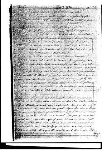
The Schedule referred to in these Letters Patent and making part of the same containing a description in the words of the said Walter Hunt himself of his improvement in the construction and manufacturing of cast iron stoves for burning Anthracite coal and other fuel which is denominated the Radiator or Plate Stove.
All to whom these Presents shall come
Be it known that I Walter Hunt of the City County and State of New York have invented or discovered and usefully improved in the arrangement and construction of a stove designed for burning coal or other fuel but more particularly adapted to the use of anthracite coal for the common purposes of heating rooms the which I distinguish by the name of the Radiator or Plate Stove and that the following is a full and exact description of the construction and operation of said Radiator or Plate Stove as invented or improved by me.
Upon a cast iron circular basis of about thirty inches in diameter stands two cast iron solid hollow columns about three inches in average diameter, twenty inches in height and about the same distance apart. Upon these columns stands a semicircular arch of cast iron made hollow and round of about three inches in diameter. The feet of said arch which rest upon the caps of said columns are formed into hollow plates about five inches in diameter which are cast in halves into with each half of the arch and are joined perpendicularly through the centre with the arch. The
Page 4.
joint being covered by a plate about three eighths of an inch wide cast into upon the edge of one half of the arch which laps its width upon the edge of the other half. The entire or crown of said arch is formed into a hollow cylinder about eight inches in height, and five in diameter, the top and bottom with a pipe about three to four inches in height, and the same in diameter projecting at right angles from the centre of said cylinder in a horizontal position and forms the tube which receives the first joint of the sheet iron pipe. Upon the tube and lower end of said small globes which forms the feet of said arches, as before described are flanchet openings about three and a half inches in diameter. Upon the outer flanchet are fitted annular cylindrical caps which cover said outer openings and binds the feet of said arch together. A ring forming a cap moulding is fitted upon the top of said crown cylinder which performs the office of help to bind the arch and crown cylinder together and forms also a band to support the water and which stands centrally upon said crown cylinder covering with its plate the upper head and opening of the same. The size is of cast iron about eight inches in height of ordinary found and its value about two years' expense. The upper shell which forms a cover to be removed at pleasure. The principle use of said arch is to contain water for evaporation. It also assists in giving a symmetrical finish to the most elevated portion of the dome. I would here recapitulate that the arch with its square parts is composed only two nearly exclusive of the rings and caps before mentioned which serve to bind said arch cylinder globes together. It is further secured by two or more rods or screws through the arch and the joint set in good cement. The rings
Page 5.
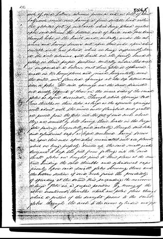
each of said hollow columns passes a rod or bolt of about half-inch round iron having a firm suitable head within the globular feet of said archs which being placed regular upon said columns the bottom end of said rods pass down through holes in the heads made centrally under the columns, and having screws cut upon their ends upon which suitable nuts are placed which on being sufficiently turned the said columns and heads are all firmly bound together in their proper positions centrally under the arch is suspended a hollow cast iron globe or spherical made in two hemispheres and joined horizontally near the centre with flanged openings at the top bottom and sides or poles. The said openings are the same dimensions and exactly opposite of those on the inner sides of the small globe as before described. Through which openings cast iron thimbles or thin tubes as large as the aforesaid openings will admit with the inner ends flanged and grated are passed from the globe into the feet of said archs where they are secured by bolts having their heads in the large globe passing horizontally and centrally through said tubes and cylindrical caps as before mentioned having screws cut upon their ends upon which convenient nuts are placed which on being properly screwed up, the said small globes designed to keep the feet from falling into the said small globes are brought firm to their places at the same time binding the said thimbles and cylindrical caps firmly upon said small globes securing them and the bottom section of said arch from the possibility of spreading at the same time suspending the enormous or large globe in a proper position by means of the above mentioned thimbles which are placed places through which a portion of the draught passes to the small globes through the arch to the crown cylindrical and pipe
Page 6.
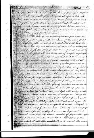
as before mentioned. The upper hemisphere of said globe is cast with a small flange upon its edge which fits snugly over that of the under one covering the joint and giving it strength to which is added brass brackets or ribs on the under side or edge of the bottom section of said globe by which means the two sections are drawn and held firmly together.
The base of the crown cylinder fits upon a corresponding flange or flanges around the opening in the top of the globe in which situation it is held and the joint connected by an annular cast iron collar forming a loop for the base of the crown cylinder and the flange of the globe. Its lower turns nearly a right angle inward and forms a special ring or collar about two inches wide and two inches diameter fitted to and encircling the upper section of the globe and onto some guides from the center floor of the stove and also the chimney pipes through which the fuel is introduced. The under hemisphere of the globe is situated about four inches below the regular curve of the globe in front of the lower section of a balloon for the purpose of aiding the descent of the ashes and accumulation of the grate. The opening is about six inches in diameter and precisely corresponds with the top of crown cylinder which is about one foot high and resting on the lower round flange with a suitable shoulder encircling its base from which extends a flange about one half inch wide perforated with ventilating holes about one and a quarter inch in diameter which is designed to admit atmosphere necessary to supply combustion. Directly over this perforated ring or flange is placed a corresponding cast iron movable ring with the same number of perforations equidistant and of similar dimensions. The office of this ring which I call the ventilator is to control the air.
Page 7.
history of the fuel in the stove when it is affected by giving it a slight eccentric movement to the right or left by which the ventilating holes are thrown open partially or entirely closed. Which is designed to supposedly control the draught of the stove and regulate its temperature of the heat. The ash pan which is under the hearth is about inches wide by inches in length to be drawn out. When it is inserted into a sheet metal box and fitted snugly to the pan open only on the side from which the pan is drawn. This box may be cast into with the hearth or separately and made of sheet iron or tin and its upper edges riveted to the bottom or under side of the hearth which is about six inches from the floor and into no part of ordinary construction.
The horizontal pipe which passes from the crown cylinder is flattened or slightly horizontally so as nearly to correspond in width with the diameter of the crown cylinder. So the bottom of the pipe is fitted a horizontal damper made to slide inward and close the draught of the crown cylinder when necessary in which case it passes wholly through the pipe into the next piping in the crown cylinder above said damper by which it is much diminished and the combustion proportionally reduced. I have varied the form and arrangement of the arches or flues of said stove by passing the horizontally around the globe forming a circular platform in which the draught passes from the globe ascending through columns into an arch to the pipe by which the structure of the stove is more elevated and more heat discharged immediately in consequence of an increased surface. I have in this case dispensed with the side column and have varied the form of the hearth in the style of a fashionable centre table bottom. I have varied the form of my grates to accommodate
Page 8.
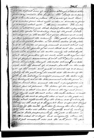
Note the different sizes of my stones although I think either size may answer both purposes. The Racks and pinion grate is constructed as follows: It is made of cast iron of a circular form about eight inches in diameter in form of a ring with the pins milled. The center hub is about one inch thick but not elevated, as projecting above the spokes to radiating bars of the grate which are deepest in the center but grow thinner and wider as they approach the extremity. This grate is placed horizontally in a horizontal position in the bottom section of the globe and to its center is firmly secured a rack about one foot in length, grated of an inch thick and two inches wide with a slot in its center nearly its whole length about three quarters of an inch wide with eight or one side of proper dimensions to write in a pinion which passes horizontally through the center column and said rack and by means of a crank-handle on the outer end of the rack and grate is raised up and down slightly or the grate may be raised into the center of the globe by the vibrating or a slight movement the ashes only are discharged and in the latter movement when the pinion is turned several times around the oral is precipitated into the ash pan at pleasure. The bottom of the rack may be soldered in a sheet iron case to secure the log work from being dragged with the orals when the center column is made. Instead of the rack a straight stone is cast on the grate circularly about eight inches long the bottom end of which fits loosely in the end of a horizontal lever suspended through the side of the center cylinder by moving this lever horizontally the ashes are shaken out properly and by working the pinion lever perpendicularly the grate is elevated in the stone when it is large and consequently allows the coal to fall around its sides into the ash pan. This open
Page 9.
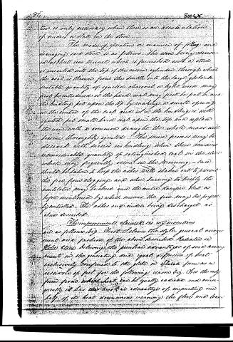
The mode of operation or manner of filling and managing said stove is as follows: The wood being removed, a short iron funnel which is furnished with a stove is inserted into the top of the common cylinder through which the coal is thrown from the double into the large globe. A suitable quantity of ignited charcoal or light wood may first be introduced in the hard coal may first be put in use. The huddling put upon the top by making a small opening in the center of the coal and when the huddling is well ignited, put small hard coal upon the top and replace the wood with a common draught. The whole mass will become thoroughly ignited. The same process may be observed with success in huddling when there remains a considerable quantity of extinguished coal in the stove which may frequently occur in the running. Care should be taken to keep the ashes well shaken out to prevent the fire from clogging, and when burning too highly the ventilator may be closed and the entire damped, that as before mentioned by which means the fire may be properly controlled. The ashes and cinders being discharged as above described.
The improvements claimed in my invention are as follows: First I claim the style, general arrangement and fashion of the above described Radiated or Globe Stove, believing the peculiar advantages of such arrangement in the generating and equal diffusion of heat exclusively confined to the globe or sphere from an reservoir of fuel for the following reasons: As the only kind from which heat can be equally radiated and consequently it has the great advantage of imparting one half of its heat downwards warming the floor and lower
Page 10.
region of atmosphere which cannot be affected by the angular or cylindrical stove.
Secondly I claim the sphere or hollow globe, or inverted hollow cone for the bottom section in particular as a reservoir of fuel and radiator of heat, in combination with the vibrating and heating grate as before specified together with the said entire hollow column which prevents the escape of ashes into the room in its descent from the globe to the grate.
Third and lastly, I claim as my improvement separately and as a part thereof the said or means of vibrating and heating grate as before specified.
In witness whereof I have hereunto set my hand this eleventh day of December 1833.
Witnesses
Wm W. Louchs
Wm G. Whelan
Drawing
(2552 words)
Published accounts: journal notice
Notice in the monthly list of patents, with remarks
Journal of the Franklin Institute, new ser., vol. 14 (1834), p. 177 · View the page
15. For a Radiator, or Globe Stove; Walter Hunt, city of New York, February 8.
Remarks. The appearance of this stove is peculiar, the body of it being a hollow globe, supported by a column, and having two columns, one on each side of it, which support an arch passing over the body of the steve. The fuel is to be put in at top, an urn that surmounts a cylindrical opening, which stands in the place of the key stone of the arch, being removed for that purpose. The grate is placed at the bottom of the globe, and consists of bars which are convex upward, and is supported by a centre shaft that descends through the column under the globe; this shaft has on it a rack, which, by means of a pinion, may cause the grate to vibrate up and down for the discharge of ashes, which fall through the column into the ash pit below. "The improvements claimed are as follows. First, the style, general arrangement, and fashion of the above described RADIATOR, or Globe Stove; believing the peculiar advantages of said arrangement in the generating and equal diffusion of heat, exclusively confined to the globe, or spheroid, form, as a reservoir of fuel, for the following reaVOL. XIV. No. 3.-SEPTEMBER, 1834. 23 American Patents for February, with Remarks. sons, viz. it is the only form from which heat can be equally radiated, and consequently it has the peculiar advantage of imparting one-half of its heat downwards, warming the floor and lower region of atmosphere, which cannot be effected by the angular or cylindrical stove. "Secondly, I claim the spheroid or hollow globe, or inverted hollow cone, for the bottom section in particular, as a reservoir of fuel, and radiation of heat, in combination with the vibrating and hoisting grate, as above specified, together with the said central hollow column, which prevents the escape of ashes into the room in its descent from the globe to the ash pan. be to the "Thirdly and lastly, I claim as my improvements separately, and as a part, the rack and pinion, or vibrating and hoisting grate, as before specified."
About this record
- Patentee
- DATAMP
- Date
- the Name and Date index of patents, DATAMP, USPTO records
- Invention
- DATAMP
- Listed in
- the Name and Date index of patents, DATAMP, USPTO records, Jim Shaw's X-patent list, the Journal of the Franklin Institute, Burke's List of Patents (1847)
- Burke's 1847 Patent Office list gives the same patent.