

Drawings and documents
National Archives restored drawings: drawing
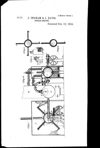
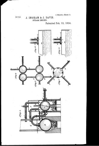
John Ingham and Julius Davis' Patent Drawing for a Steam Engine


National Archives, Restored Patent Drawings (Record Group 241) · Full-size scan at the National Archives · Catalog record
Show the text on the drawing Hide (297 words)
Words on the drawing as machine-read by the National Archives; not checked. Useful mainly for searching.
Sheet 1. EAM. / ENGINES. / 50] Rotary. / Ingham Davis's / 25heets Sheet2. 1 / Pat, Feb,12 1834 / CLASSI TO / Steam Engine / 8019-+ X / DIVISION. / Jig.9. / Tig.10 / of / h- / of / Tigl. / feait.
Sheet 2. 201 / 2 Sheots Sheet / John Ingham you Julius Davis. / CHARTING / YOU / 8019-+ / Steam Engine. / Vol.18. by. 591. / DIVISION. / Patented Ash. 12. 1834. / OF / thig3. / Fig.1. / Tig.2. / Higs / Sigh / in / la / References. a the metallic globe with four steam arms. b.b hallow shaft. C.C C.C. orifices. d.d.d.d arms. e'e". steam pipes. of division plate in the 7.6 / g. the moving or sliding valve. h. h friction rollers see Fig 6. i the endless serew. K what and enfless serew. l wheel. m the boiler. / Paint office 30th Septems 1841 / n. n fireboses. 0 flue from the furnace. p.p. smoke peper q chimney r.r.r Regulating values. s the Sacket. t. pipe for the escapestiam/made under the direction of the Commissioner of / febit. Plate I Tig and i. interior view of the engine, one sideofthe Jacket andowide of they lire box n is removed, to show the arrangement. Jig2 Lection of the Jacket Patents in confirmity with act of 32) march180 / fire box flue and smoke piped. Fig 3 Jide view of an apparatus with 2 globes Tigh section af globe Fig.3. Sig 5 a whole apparatus. / Plate II. Sig. 6 lection of boiler furnace Jacket, boxes glabe and shafts. Fig.7 the globeand apm cut through the centre showing the dioision platef. / Myny LSumorth / fig 8x.g. two globes Jig of the sectional fy. 8. big 10 Section of boiler & liding value, letting the steam on one pipe. Fig 11 Section of boiler and / Commissioner of Patents. / sliding valve, letting the steam on both pipes, to stope the revolving globe and shaft.
USPTO scan
The patent as scanned by the USPTO
-
 Page 1
-
 Page 2
-
 Page 3
-
 Page 4
-
 Page 5
-
 Page 6


U.S. Patent and Trademark Office · Google Patents
Show the transcription Hide (1,782 words)
Machine transcription (LightOnOCR) of the pages as scanned by the USPTO, most of them the handwritten copies made when the records were restored after the 1836 fire. Not checked; it can misread handwriting, so compare it with the scan.
Page 1.
8019X
J. INGHAM & J. DAVIS.
STEAM ENGINE.
Patented Feb. 12, 1834.
2 Sheets—Sheet 1.

Page 2.
8019X
J. INGHAM & J. DAVIS.
STEAM ENGINE.
Patented Feb. 12, 1834.
2 Sheets—Sheet 2.

Page 3.
2/12/1834 8019X
No. 15
Feb. 12, 1834
591
John Ingham & Julius Davis, Inventors. N. York.
Letters Patents
The Schedule referred to in these Letters Patent, and making part of the same containing a description of the works of the said John Ingham and Julius Davis themselves of their improvement in the use and application of Steam & the endless screw and in the apparatus for propelling machinery by steam.
To all to whom these presents shall come
We do know that the John Ingham & Julius Davis of Julius in the County of Onondaga in the State of New York have invented certain new and useful improvements in the use and application of Steam; and the use and application of the endless screws and in the machinery and apparatus to be used in propelling machinery by steam of which the following is a description.
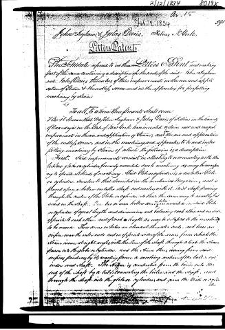
First. Said improvements consist in attaching to or connecting with the hollow globe or cylinder formerly invented such machinery as may be necessary to operate all kinds of machinery. Said Globe or cylinder is a metallic Globe or cylinder, similar to that described in the Mechanics Magazine, and is placed upon a hollow metallic shaft and revolves with it. Said shaft passing through the center of the Globe or cylinder, so that the same may be revolved but used on the shaft. One two or more hollow arms or tubes are inserted in said Globe or cylinder of equal length and dimensions and balancing each other and on side opposite to each other, and of such a length as may be adapted to the machinery to be moved. These arms or tubes are elongated through ends, and have no orifices near the outer ends and on opposite sides of the arms from which the steam issues at right angles with the line of the shaft through which the steam passes into the Globe or cylinder, and the steam thus issuing from said orifices produces by its reacting force a revolving motion of the ball or cylinder and shaft. The steam is conducted from the boiler into the end of the shaft by a tube connecting the boiler and the shaft, and through the shaft into the globe or cylinder and from the Globe or cylinder.
Page 4.
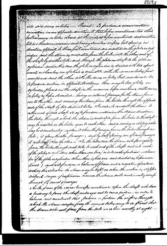
into said arms or tubes — Second. To produce a reverse motion or motion in an opposite direction to that before mentioned two other hollow arms or tubes closed at the ends as before mentioned and constructed in the same manner and having similar orifices but opening in directions opposite to those first mentioned are inserted in the globe or cylinder and the steam is conducted from the boiler into the other end of the shaft by another tube and through the globe or shaft to the globe or cylinder, and in this case the globe or cylinder is divided into two apartments or chambers, one of which is connected with the arms or tubes first mentioned and the other with the arms or tubes last mentioned: or to produce motion in opposite directions, there may be two globes or cylinders placed on the shaft in the manner before mentioned with arms or tubes as before described, having no internal passage for the steam from one to the other, and receiving the steam from the boiler through the opposite ends of the shaft by two distinct tubes, or to order to conduct the steam to either end of said shaft so as to produce motion in the desired direction, the tubes through which the steam is conducted from the boiler to the shaft may be inserted in the boiler near to each other, and a moving or sliding valve may be constructed so when it closes the passage from the boiler through one tube; it opens the other passage, and by half opening one of said passages it will half close the other — or in the latter case the steam will pass equally from the boiler through each tube to each end of the shaft and into each of the globes or cylinders when there are two (or into each apartment or chamber of the globe or cylinder when there is but one and divided as before mentioned) and will produce a balance of force and a cessation of motion, and in this situation the steam may be kept on when the motion is stopped without danger of explosion because the steam will continually escape through its usual passages.
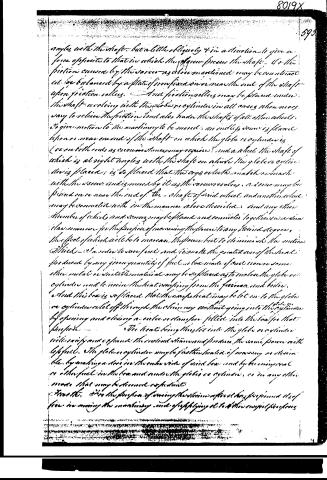
As to the force of the screw hereafter mentioned, upon the shaft will have a tendency to press the shaft endways and to cause friction in order to balance and counteract that friction or friction the orifices through which the steam passes from the arms or tubes may be so placed that the steam will not pass from the tube in a line nearly at right
Page 5.
angles with the shaft, but a little obliquely & in a direction to give a force opposite to that in which the gear presses the shaft. Or the friction caused by the screw as above mentioned may be counteracted or balanced by a plate of iron fixed on or near the end of the shaft upon friction rollers. And friction rollers may be placed under the shaft revolving with the globe or cylinder in all cases when necessary to relieve the friction and also under the shafts of all other wheels.
To give motion to the machinery to be moved, an endless screw is placed upon or near an end of the shaft on which the globe or cylinder is (or on both ends as circumstances may require) and a wheel the shaft of which is at right angles with the shaft on which the globe or cylinder is placed; is so placed that the cogs or teeth match or mesh with the screw and is moved by it as the screw revolves. A screw may be placed on or near the end of the shaft of said wheel and another wheel may be connected with in the manner above described, and any other number of wheels and screws may be placed and connected together in a similar manner for the purpose of increasing the power to any desired degree.
The effect of which will be to increase the power but to diminish the motion thereof. In order to save fuel and to make the greatest use of the heat produced by any given quantity of fuel, a box made of iron or some other metal or suitable material may be so placed as to inclose the globe or cylinder and to inclose the heat escaping from the furnace and below. And this box is so placed that the excess of heat may be let on to the globe or cylinder and let off through the chimney without going into the cylinder by opening and closing a valve or stopper fitted into the box for that purpose.
The heat being thus let into the globe or cylinder will rarify and expand the enclosed steam and produce the same power with less fuel. The globe or cylinder may be so situated as to be heated, if necessary, as desired by making a stove in the under side of said box and by burning coal or other fuel in the box and under the globe or cylinder, or in any other mode that may be deemed expedient.
Lastly, it is the purpose of saving the steam after it has performed its office in moving the machinery and of applying it to other useful purposes.
Page 6.
8019X
594.
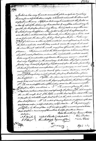
a jacket or box may be made around the globe or cylinder & enclosing the same from which the steam escapes which will receive all the steam as it escapes from the same. A pipe or tube may be inserted into this jacket or box by which the steam may be conducted to any place where it may be wanted for the purpose of warming Rooms, boiling water or any other use to which it may be applied. This jacket or box is to be so placed as to receive the steam without receiving the smoke from the furnace or boiler and so as to prevent the steam from falling back upon the fire & chimney may be made of steel iron or other suitable material, and so placed as to enclose the globe or cylinder and the boxes made to receive the escape heat and the steam through which the smoke may pass off and the steam about pleasure. The furnace in which the Globe and cylinder & boilers are placed should be made of cast iron or some other incombustible material and the boiler may be constructed and placed in the common manner, and the heat may be applied in the usual way to the boiler. This Engine and apparatus may be used for propelling boats & vessels upon the water, for working all kinds of mills and manufactories, for mining carriages on rail roads and on the land; for mining vessels upon marine Railways, and for moving all heavy bodies and for all other purposes to which steam power can be applied.
2ndly. The claims as mentioned contain improvements made but not mentioned in the foregoing specification the following things.
1st The use and application of the engine more in the manner and for the purposes before mentioned.
2nd The manner of giving the globe or cylinder a revolution and especially the placing of the globe or cylinder in the escape heat of the boiler and other heat as before stated & the mode or manner by which the escape heat is let into the globe or cylinder & directs from it at pleasure.
3rd The method of changing the direction & application of the steam to produce motion in different directions as before described.
4th The producing of a greater force for the use of steam with less expense of fuel or machinery and with less danger of explosion than in many of the methods heretofore in practice or known.
Witnesses
J. F. Heigler
C. O. Wright
Walter Clarke
Geo. A. Mellingly
John S. Simpson
C. W. Davis
C. A. C.
Drawing
1905 11-27
Published accounts: journal notice
Notice in the monthly list of patents, with remarks
Journal of the Franklin Institute, new ser., vol. 14 (1834), p. 182 · View the page
26. For the Application of Steam and an Endless Screw in Propelling Machinery; John Ingham, and Julius Davis, Fabius, Onondaga county, New York, February 12.
Remarks. The patentees allude to a globe, or cylinder, steam apparatus of their invention, and described in the Mechanic's Magazine; we, howAmerican Patents for February, with Remarks. ever, need not refer to this, but shall describe the instrument as patented. A hollow shaft is to revolve on gudgeons, and a part of this shaft is to be enlarged so as to form a globe, or cylinder. From this globular part, arms are to project at right angles to the axis of the shaft, which arms are to have orifices at their sides, near to their extremities, from which steam, admitted into the shaft, is to issue, and, by its reaction, to cause the shaft to revolve. There may be four such arms, in two of which the orifices may be so made as to operate in a different direction from the other two, there being a suitable division in the globe, or cylinder, to govern the steam in its course to either pair of arms. Steam may be admitted into either end of the shaft from an ordinary boiler, and, to increase the elasticity of this steam, it is proposed to admit a portion of the waste heat from the furnace into a case, or box, surrounding the globular body. Fire, if required, may also be made within this box, with the same view; this constitutes the steam part of the machinery. In order to use the power thus generated, there is to be an endless screw upon the shaft, which is to gear into a toothed wheel, from the shaft of which the desired communication may be made. This engine, we are told, may be used for propelling boats, for driving mills, for moving carriages upon rail-roads, raising vessels on marine rail-ways, &c. &c. The claims are to the use and application of an endless screw in the manner, and for the purposes mentioned; the manner of using the globe, or cylinder, and exposing it to the escape heat of the boiler; and a valve, or damper, by which the escape heat is directed upon, or diverted from, the globe; the method of changing the direction of the motion; and "the producing of a given degree of power by the use of steam with less expense of fuel or machinery, and with less danger of explosion, than in any of the methods heretofore practised or known." Although this engine may be used for the various purposes designated, such an employment of it will not be the result of an intimate acquaintance with steam power, or that of mechanical arrangement. A less efficient way of using the former has rarely been proposed; and why this power should operate through the intervention of an endless screw, it would not be easy to tell, unless there is some hidden mystery in its action, with which we are unacquainted. A pinion, or spur wheel, upon the shaft, would prevent all that lateral thrust from the screw, to counteract the effect of which the patentees throw away a corresponding portion of their steam power, by making the orifices on the arms oblique, that the steam may issue in a direction which will counteract the thrust.
About this record
- Patentee
- DATAMP
- Date
- the Name and Date index of patents, DATAMP, USPTO records
- Invention
- DATAMP
- Listed in
- the Name and Date index of patents, DATAMP, USPTO records, Jim Shaw's X-patent list, the Journal of the Franklin Institute, Burke's List of Patents (1847)
- The X number corrects a misprint or misreading in one of the sources.
- Burke's 1847 Patent Office list gives the same patent.