

Drawings and documents
National Archives restored drawings: drawing
David H. Gilbert's Patent Drawing for a Water Wheel

National Archives, Restored Patent Drawings (Record Group 241) · Full-size scan at the National Archives · Catalog record
Show the text on the drawing Hide (59 words)
Words on the drawing as machine-read by the National Archives; not checked. Useful mainly for searching.
188. HYDRAULIC MOTORS / Turbins / [W0] / Top-Ring Supply. / All / COMMISSION / 8034. / wheel. / DIVISION. / Pa ented 28 th Feb! 1834. / FIG. 1, / B. / FIG. 2. / FIG.3. / A. / f. / B. / B. / D. / f. / G. / f. / d. / f. / f. / A. / A. / a. / a. / A. / A. / FIG / FIG 4. / C. / l. / l. / C. / C. / D. / 1.
USPTO scan
The patent as scanned by the USPTO
-
 Page 1
-
 Page 2
-
 Page 3
-
 Page 4
-
 Page 5


U.S. Patent and Trademark Office · Google Patents
Show the transcription Hide (1,459 words)
Machine transcription (LightOnOCR) of the pages as scanned by the USPTO, most of them the handwritten copies made when the records were restored after the 1836 fire. Not checked; it can misread handwriting, so compare it with the scan.
Page 1.
8034X
D. H. Gilbert,
Water Wheel,
Patented Feb. 28, 1834.
Fig. 1.
Fig. 2.
Fig. 3.
Fig. 4.
Fig. 5.
Page 2.
Feb. 28, 1834
David H. Gilbert of Dorchester, Massachusetts
Letters Patent
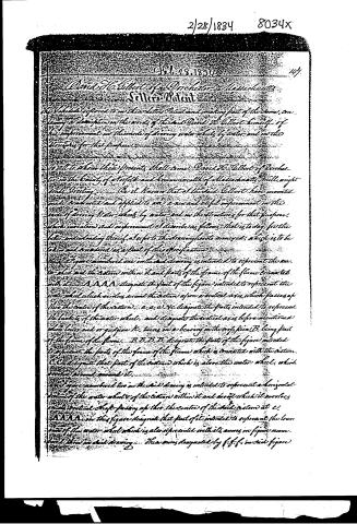
The undersigned referred to in their Letters Patent and making part of the above, containing a description in the words of the said David H. Gilbert himself, of his improvement in the mode of driving water wheels by water and in the structures for that purpose.
It will to show their present, shall come: David H. Gilbert of Dorchester in the County of Norfolk and Commonwealth of Massachusetts, will right hereby stating: Be it known that I, David Gilbert, have invented and constructed and applied to use a new and useful improvement in the mode of driving water wheels by water and in the structures for that purpose, which invention and improvement I describe as follows: that is to say, for the better understanding thereof, I refer to the drawings hereto annexed, which is to be taken and considered as a part of this specification.
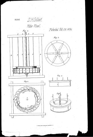
In the figure numbered one in the said drawing is intended to represent the water wheel and the piston within it and parts of the frame of the flume connected with it. A A A A designate the part of the figure intended to represent the water wheel which revolves around the piston upon a vertical axis, which passes through the centre of the piston. a. a. a. b. c. designate the parts intended to represent the buckets of the water wheel, and designate the vertical axis before mentioned which lower end or guide R, turns on a bearing on the workpiece B, being part of the frame of the flume. B B B B designate the parts of the figure intended to represent the parts of the frame of the flume which is connected with the piston. C C designate that part of the piston which is above the water wheel, which revolves around around it.
In the figure numbered two in the said drawing is intended to represent a horizontal section of the water wheel & of the piston within it and around which it revolves upon a vertical shaft passing up through the centre of the said piston at e. A A A A in this figure designate that part of it intended to represent the lower end of the water wheel which is also represented with its arms in figure one and three in said drawing. These arms designated by f. f. f. in said figure
Page 3.
8034X
145
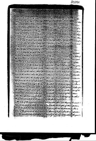
smaller than those in the lower row, and are the only ones of the whole. The upper rows of the wheel is not shown in the figure numbered two, in order that the buckets may be exhibited which are between the upper and lower rows fixed in grooves made in the rims. These buckets are in the form of a cone, as represented in the figure numbered two, which form is deemed best although they may be made in the form of an elbow, or in what different shape to answer the purpose tolerably well. On a wheel of ten feet in diameter, these buckets may be about nine inches apart; but they may be farther or nearer from or to each other as occasion may require according to the size of the wheel, and the quantity of water to be let upon it, as occasion may require.
The buckets are designated by a a a a in the said figure numbered two.
b b b b designate the parts of the said figure numbered two, intended to represent the sides of the said cisterns around which the water wheel is to revolve. These sides of the cisterns are so constructed that parts of them from d d to m, left over each other, so as to leave apertures in the form of a cone from the inside of the cistern at d d to the outside of the cistern at m m, which, when the gates d d c c c c are open the water in the cistern may issue and strike upon into the buckets of the wheel. These apertures are to be made larger at the mouth inside of the cistern when the gates are, than at the outside at m m, where the water issues upon the buckets of the wheel, and should gradually decrease in size from d d to m m, as represented in the figure numbered two. They may be larger or smaller according to the size of the wheel and the power required. For a wheel ten feet in diameter with buckets fifteen inches in length and nine inches apart the apertures may be about eight inches wide at the mouth d d, on the inside of the cistern, and about four inches wide at the mouth m m, outside of the cistern. But these apertures may be larger or smaller according to the size of the wheel, the quantity of water to be let upon it and the power required.
The sides of the cisterns are made to lap over each other, and they may be made to lap over as much as about two feet, so as to make the length of these apertures about two feet; but they may be made longer or shorter at discretion. For a wheel of the dimensions above stated, there may be from four to six apertures, but the number may be varied or left according to the size of the wheel, the quanti-
Page 4.
of water to be let inwards, and the power required. The arms of a wheel of the above dimensions, should be about fifteen inches apart, so that the buckets may be about fifteen inches long, and on this account the apertures may be about fifteen inches high. The head height with the length of the buckets of the wheel 5 5 5 5, depending on the state of the water. These gates must correspond in number with the apertures of the box, requisite to regulate and alter the power and speed of the wheel from hour to hour, but otherwise these gates may be dispensed with, and a main gate to the flume connected with the cistern will answer very well. The course of the water thru' the apertures is intended to be represented by the arrows on fig. are numbered two. The top of the cistern should be about ten inches above the level of the water wheel, the lower part being above the top of the water wheel. The upper sides of the water wheel is the inner edges of the teeth of the water wheel and the sides of the cistern should be so adapted to each other that the wheel may revolve around the cistern as nearly and closely to it as it can conveniently be made to do without friction. D. designates the bottom of the cistern for receiving and containing the water to be let out thru' the apertures upon the backs of the water wheel. The cistern is somewhat like Wing's cistern which is represented in one of the figures in the second volume of the journal of the Franklin Institute at page eighty seven. Another view of this cistern is given in figure numbered five in said drawing. The rim which covers the top of the said aperture is cast from a sort of conical tube from the pole at the inner mouth A. to the outer mouth N. as seen in the figure being designated by l. l. l. l. The gates are represented as before by c. c. c. P. the lines of the gates by 5 5 5 5, by the turning of which the gates are to be opened or shut, or partly opened or shut at pleasure. These gates however may be made so as to be opened by hoisting P. on, to spread the outer mouth of the aperture. The flume is immediately above the cistern, and is adapted to it so as to fit to it water tight, in order to prevent the escape of water. The flume must be large enough to keep up the head of water required to act upon the wheel. For a wheel of the above dimensions, a flume about twelve feet wide and about fifteen feet in length will answer the purpose. The buckets of the wheel should be of metal, as well as the arms and shaft and the whole wheel and cistern may also be of metal as the wood will an
Published accounts: journal notice
Notice in the monthly list of patents, with remarks
Journal of the Franklin Institute, new ser., vol. 14 (1834), p. 191 · View the page
44. For an improvement in Water Wheels; David H. Gilbert, Dorchester, Norfolk county, Massachusetts, February 28.
Remarks. We have here again the reaction water wheel, which we have so frequently described, and differing but little from some of those previously noticed; and, in most of those cases where there is some apparent variations, the observation is made, that it is not necessary to make the parts spoken of in this form. The gates for closing the apertures of the buckets, although similar in the effect produced, by them, differ in their mode of action from those formerly noticed, but as there is nothing claimed but "the construction and use of such wheels as above described, and such cisterns within them, in connexion and combination with each other," we really do not know what it is intended to patent.
About this record
- Patentee
- DATAMP
- Date
- the Name and Date index of patents, DATAMP, USPTO records
- Invention
- DATAMP
- Listed in
- the Name and Date index of patents, DATAMP, USPTO records, Jim Shaw's X-patent list, the Journal of the Franklin Institute, Burke's List of Patents (1847)
- Burke's 1847 Patent Office list gives the same patent.