

Drawings and documents
USPTO scan
The patent as scanned by the USPTO
-
 Page 1
-
 Page 2
-
 Page 3
-
 Page 4
-
 Page 5


U.S. Patent and Trademark Office · Google Patents
Show the transcription Hide (1,336 words)
Machine transcription (LightOnOCR) of the pages as scanned by the USPTO, most of them the handwritten copies made when the records were restored after the 1836 fire. Not checked; it can misread handwriting, so compare it with the scan.
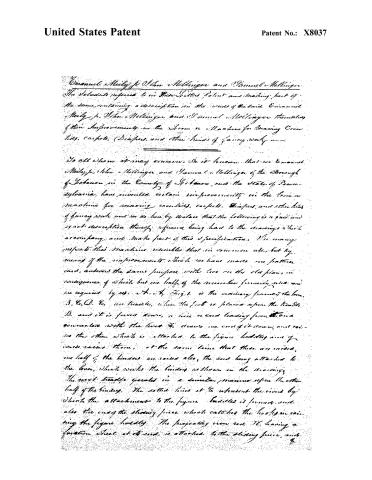
Page 2.
United States Patent
Patent No.: X8037
Emmanuel Meily, Jr., John Hellinger, and Samuel Hellinger
The following is referred to in this Patent and making part of the same, containing a description in the words of the said Emmanuel Meily, Jr., John Hellinger, and Samuel Hellinger themselves of their Improvements in the Loom or Machine for Weaving Cotton, Wool, Carpets, (Drapes, and other kinds of fancy work.
To all whom it may concern, Be it known that we Emmanuel Meily, Jr., John Hellinger, and Samuel Hellinger of the Borough of Lebanon in the County of Schuylkill, and the State of Pennsylvania, have invented certain improvements in the Loom or machine for weaving carpets, carpets, Drapes, and other kinds of fancy work, and we do hereby declare that the following is a full and exact description thereof, reference being had to the drawings which accompany, and make part of this specification. In many respects this machine resembles that in common use, but by means of the improvements which we have made, one pattern card, answers the same purpose with two in the old plan, in consequence of which but one half of the mechanism formerly used, and as required by us. A. B. Fig. 1. is the ordinary frame of the loom. B. C. D. E. are trundles, when the foot is placed upon the trundle B. and it is forced down, a wire or cord leading from it and connected with the trundle F. draws one end of it down, and raises the other, which is attached to the figure holding arm of the loom, at the same time that these are raised, one half of the binders are raised also, the cord being attached to the lever, which works the binders as shown in the drawings. The next trundle operates in a similar manner upon the other half of the binders. The dotted lines at G. represent the wires by which the attachments to the figure holdles is formed, and also the end of the sliding piece which catches the hook in raising the figure holdles. The projecting iron rod H. having a friction wheel at its end, is attached to the sliding piece, and
Page 3.
United States Patent
Patent No.: X8037
of course, rises with it. On so doing, the friction roller is brought into contact with the curved spring piece L. The lower end of which is attached to what we call the swinging frame J. These parts are all double, that is they are repeated at the opposite end, and of course are not seen in the drawing. The needle beam K turns in the swinging frame, below the swinging frame there is a cam L, which enters upon pins upon the wheel M. There being four such pins, at equal distances apart, the cam is shown in the drawing acting upon one of them, and the needle beam is in operation with the pattern, early. When the swinging frame is thrown forward the cam L catches upon the next pin, not seen in the drawing, being hidden by the swinging frame, the needle beam is of course one front of the way round at every other forward swing of the swinging frame.
Behind the wheel M, and on the same shaft with it there is in Fig. 2, M, being the round and N, the oval wheel. These two wheels are shown in the hooks O & P. The round and oval wheels are solely intended to operate upon the needle beam. The situation in which the hooks O & P stand in the drawing results from their being separated by the contact of the longest diameter of the oval wheel. When the swinging frame moves forward being set into operation by one of the figure needles, the needle beam and pattern end on it, remain in the same situation. In the return of the swinging frame, the cam L catches one of the pins on the round wheel M, before mentioned, and turns both wheels in opposite round and consequently the figure hook C, catches upon the shortest diameter of the oval wheel, and at its extremity, takes hold of the needle beam, at the second swinging forward of the swinging frame, being set into motion by the other figure needle, the needle beam being held by the hook C, would turn round one fourth and presents a new pattern end towards the needle. A and Q connect the outer ends of the two hooks O & P. The weight R, has a rod attached to it, which passes over a pulley at the upper part of the machine and is connected with the hooks O & P as seen in the drawing.
D. When
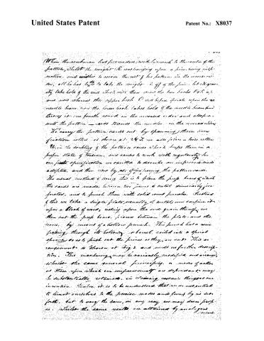
Page 4.
United States Patent
Patent No.: X8037
When the workman has proceeded with his work to the extent of the pattern, whilst the weights (it was hanging upon a fine, heavy rope, and neither to escape the rest of his pattern in the course of the work, all he has to do to take the weights off of the fine, let a gravity take hold of the cord which will then swing the two hooks (A & B) up and into where the upper hook C will before spiral upon the needle beam, now the lower hook takes hold of the needle beam and brings it one fourth round in the reversed order and also presents the pattern — cards towards the needle, in the reversed order.
We carry the pattern cards out by spanning them over friction rollers, as shown at 1, 2, 3, 4, 5, 6, 7, 8, 9, 10, 11, 12, 13, 14, 15, 16, 17, 18, 19, 20, 21, 22, 23, 24, 25, 26, 27, 28, 29, 30, 31, 32, 33, 34, 35, 36, 37, 38, 39, 40, 41, 42, 43, 44, 45, 46, 47, 48, 49, 50, 51, 52, 53, 54, 55, 56, 57, 58, 59, 60, 61, 62, 63, 64, 65, 66, 67, 68, 69, 70, 71, 72, 73, 74, 75, 76, 77, 78, 79, 80, 81, 82, 83, 84, 85, 86, 87, 88, 89, 90, 91, 92, 93, 94, 95, 96, 97, 98, 99, 100.
In the doubling of the pattern cards which keeps them in a proper state of tension, and causes to work with regularity. In our first specification we omitted to describe an improved mode adopted, and then used by us, of preparing the pattern cards.
The usual method of doing this is to place the pulp board of which the cards are made, between two pieces of metal, similarly perforated, and to punch them with solid round punches. Instead of this we take a single plate usually of metal, and confine it upon a block of wood, resting upon the end grain thereof, we then cut the pulp board, placed between the plate and the wood, by means of a hollow punch. This punch has a wire passing through its hollow, or barrel, coiled into a spiral spring so as to push out the pieces as they are cut. This arrangement is shown at figs 3, and needs no further description. This machinery may be variously modified and arranged, whilst the same general principles, or modes of action, at those upon which our improvements are dependent, may be substantially retained. In claiming certain things as our invention, therefore, it is to be understood that we do not intend to limit ourselves to the precise modes and forms by us set forth, but to vary the same, in any way we may deem proper, whilst the same results are attained by analogous means.
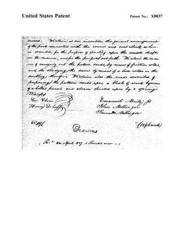
Page 5.
United States Patent
Patent No.: X8037
We claim as our invention the general arrangement of the parts connected with the round and oval wheels, as here so described, for the purpose of operating upon the needle shaft, in the manner, and for the purposes set forth. We claim the manner of carrying out the pattern cards, by means of friction rollers, and the steadying the same by means of a loose roller on the doubling thread. We claim also the mode described of preparing the pattern cards upon a block of wood by means of a hollow punch and cleaver operated upon by a spring.
Witnesses:
Geo. Klein
Henry Dehuff
Emanuel Meily Jr
John Mellinger
Samuel Mellinger
60 M.C.
Drawing
(1246 words)
(Rec’d 24. April 1897. & Recorded anew —)
Published accounts: journal notice
Notice in the monthly list of patents, with remarks
Journal of the Franklin Institute, new ser., vol. 14 (1834), p. 232 · View the page
3. For a Loom for Weaving Coverlids, Carpets, and all kinds of Fancy Work; Emanuel Meily, jr., John Mellinger, and Samuel Mellinger, Lebanon, Lebanon county, Pennsylvania, March 1.
Remarks. In this loom there is some simplification of the arrangement of those parts by which the pattern is produced, although the general principle of such looms remains unchanged. The claims made refer to figures on the drawing, and do not admit of a description that would be understood by one not perfectly conversant with such machinery.
Published accounts: journal notice
Notice in the monthly list of patents
Journal of the Franklin Institute, new ser., vol. 17 (1836), p. 56 · View the page
"Now what I claim as my own invention and not previously known, in the above described machine, is the discharging of the steam on the outside of the rim of a tight enclosed circular wheel, at the greatest possible distance from the axis, or shaft, by which an increase of power is gained over any other rotary engine," &c. &c. 69. For improvements in the Loom for Figured Work; E. Meily, jr. and J. & S. Mellinger, Lebanon, Lebanon county, Pennsylvania: first patented March 1st, 1834.
About this record
- Patentee
- DATAMP
- Date
- the Name and Date index of patents, DATAMP, USPTO records
- Invention
- DATAMP
- Listed in
- the Name and Date index of patents, DATAMP, USPTO records, Jim Shaw's X-patent list, the Journal of the Franklin Institute, Burke's List of Patents (1847)
- Burke's 1847 Patent Office list gives the same patent.