

Drawings and documents
National Archives restored drawings: drawing
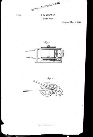
Benjamin E. Stickney's Patent Drawing for a Agricultural Pulverizer

National Archives, Restored Patent Drawings (Record Group 241) · Full-size scan at the National Archives · Catalog record
Show the text on the drawing Hide (41 words)
Words on the drawing as machine-read by the National Archives; not checked. Useful mainly for searching.
Entered / 97. PLOWS, / Rotary Cultivators. / BENJAMIN F. STICKNEY'S / CLASSIFICATION / 8039-+ / Agriculíural Pulverizer. / DIVISION. / Parented March 1834 / Rot Cult / Top / View. / Mig:1. / TF, / Side View, / Hig:
USPTO scan
The patent as scanned by the USPTO
-
 Page 1
-
 Page 2
-
 Page 3


U.S. Patent and Trademark Office · Google Patents
Show the transcription Hide (606 words)
Machine transcription (LightOnOCR) of the pages as scanned by the USPTO, most of them the handwritten copies made when the records were restored after the 1836 fire. Not checked; it can misread handwriting, so compare it with the scan.
Page 1.
No Printed Specification Available
8039X
B. F. STICKNEY.
Steam Plow.
Patented Mar. 1, 1834.
Fig. 1.
Fig. 2.
AN. PHOTO-LITHO. CO. N.Y. (OSBORNE'S PROCESS.)
Page 2.
3/1/1834 8039X
Mar. 1, 1834 45
Benjamin F. Stickney, Michigan.
Letters Patent. Mar. 1, 1834.
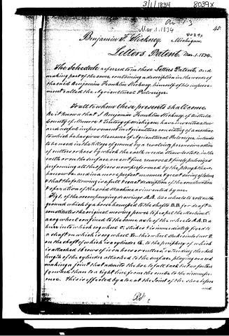
The Schedule referred to in these Letters Patent, and making part of the same, containing a description in the words of the said Benjamin Franklin Stickney, himself of his improvement called the Agricultural Pulverizer.
To all to whom these presents shall come.
Be it known that I Benjamin Franklin Stickney, of Kistaca County of Illinois & Territory of Michigan, have invented a new and useful improvement in Agriculture consisting of a machine to which he has given the name of Agricultural Pulverizer, intended to be used in the tillage of ground by a revolving percussionation of cutters or hoes by which the earth weeds, stone-roots &c. in the earth or on the surface are cut fine removed & finely pulverized performing all the offices now performed by the plough, harrow &c. and in a more perfect manner & great saving of labor & that the following is a full & exact description of the constitution & operation of the said Machine as invented by me.
Fig 1. of the accompanying drawings A.A. two wheels to roll on the ground which by a horse harnessed to the shafts B.B. for draft constitutes the original moving power to propel the Machine C. a cog wheel confined to the same axle of the wheels A.A. D. a bevel into which cog wheel C. sticks & is immediately fixed to a shaft on which is a cog wheel D. this wheel sticks into bevel E. on the shaft of which is a cylinder G. to the periphery of which is attached 16 rows of iron hoes or cutters extending the whole length of the cylinder attached to the surface playing on and making a joint that admits the hoe to fall back but no farther from the stone to a right line from the center to the circumference. This is effected by a toe at the joint of the shoe before
Rd.
Page 3.
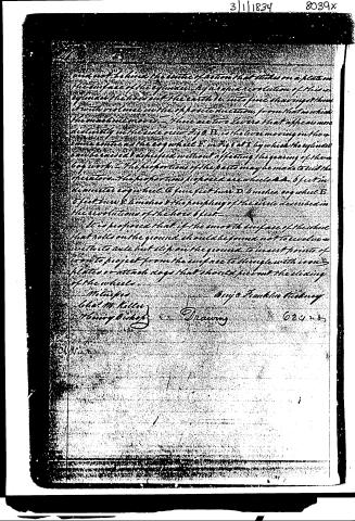
and not behind the center of action that strikes on a plate on the surface of the cylinder. By a rapid revolution of this cylinder the holes cut the earth into fine shavings & thus it will be rolled in the opposite direction from that in which the machine moves. There are two levers that appear more distinctly in the side view Fig. B. is the lever moving on the same center as the cog wheel E. in Fig. 1 at I by which the cylinder can be raised & depressed without affecting the gearing of the box work. The proportions of the parts may be made to suit the operator. The proportions of the gears are wheels A A. 6 feet in diameter cog wheel C 6 feet 6 inches, cog wheel E 5 feet 6 inches & the periphery of the circle described in the revolution of the holes 6 feet.
It is proposed that if the smooth surface of the wheel that rolls on the ground should be found not to revolve with its axle but slip on the ground to insert points of iron to project from the surface to engage with iron plates or attach dogs that should prevent the sliding of the wheels.
Witnesses
Benj. Franklin Nickney
John M. Kelly
Henry Bishop
Drawing 624285
3/1/1834 8039x
Published accounts: journal notice
Notice in the monthly list of patents, with remarks
Journal of the Franklin Institute, new ser., vol. 14 (1834), p. 232 · View the page
4. For an agricultural instrument called an Agricultural Pulverizer; B. F. Stickney, Vistula, Monroe county, Michigan Territory, March 1.
Remarks. There is a striking resemblance between this machine and that patented by Mr. Jas. D. Woodside, on the 28th of July, 1832, the main difference being in making the part which is to pulverize the ground, in the form of cultivator teeth, and allowing them to fall back by means of a hinge joint close to the roller, whilst in Mr. Woodside's machine they are permanent teeth, or spikes. The roller around which the cutters, or hoes, are fixed, receives its motion by gearing from wheels which roll upon the ground, and there is a lever to raise or depress the roller, as in the former machine. It is also proposed to place spikes or pins on the faces of the wheels which run upon the ground, should the friction not be sufficient to drive the roller with its cutters. There is no claim made. We have alluded to Mr. Woodside's patent, but find that our notice of it was accidentally omitted in its proper place; but as this instrument is now coming into use, we design, at an early day, to place the specification of it, with a cut, before our readers.
About this record
- Patentee
- DATAMP
- Date
- the Name and Date index of patents, DATAMP, USPTO records
- Invention
- DATAMP
- Listed in
- the Name and Date index of patents, DATAMP, USPTO records, Jim Shaw's X-patent list, the Journal of the Franklin Institute, Burke's List of Patents (1847)
- Burke's 1847 Patent Office list gives the same patent.