

Drawings and documents
National Archives restored drawings: drawing
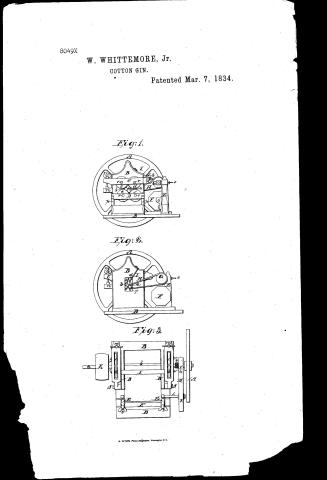
William Whitmore, Jr.'s Patent Drawing for an Improvement in the Cotton Gin

National Archives, Restored Patent Drawings (Record Group 241) · Full-size scan at the National Archives · Catalog record
Show the text on the drawing Hide (54 words)
Words on the drawing as machine-read by the National Archives; not checked. Useful mainly for searching.
Colton gins / apr,Products / 13. BRAKES & GINS. / Roller Gins. / William Whittemore / p2- / CLASSIFICATION / Imp Cotton Cuin / and / 8049- X / Patented March 7th 1834. / DIVISION. / Fig 1. / GO / F' / Fig2. / VL / 4H / VA / Fig3. / OF / we / in / is / 5.8 / II / Γ. / RS
USPTO scan
The patent as scanned by the USPTO
-
 Page 1
-
 Page 2
-
 Page 3
-
 Page 4
-
 Page 5
-
 Page 6
-
 Page 7
-
 Page 8
-
 Page 9
-
 Page 10
-
 Page 11


U.S. Patent and Trademark Office · Google Patents
Show the transcription Hide (3,269 words)
Machine transcription (LightOnOCR) of the pages as scanned by the USPTO, most of them the handwritten copies made when the records were restored after the 1836 fire. Not checked; it can misread handwriting, so compare it with the scan.
Page 1.
8049X
W. WHITTEMORE, Jr.
COTTON GIN.
Patented Mar. 7, 1834.
Fig: 1.
Fig: 2.
Fig: 3.
N. PETERS, Photo-Lithographer, Washington, D.C.
Page 2.
5771834 8049x
Mar 7, 1834 263
William Whittemore
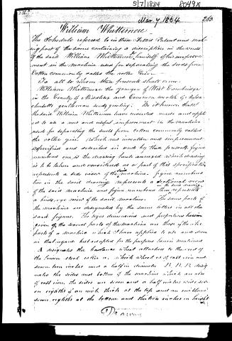
The Schedule referred to in these Letters Patent and making part of the same containing a description in the words of the said William Whittemore himself of his improvement in the machine used for separating the seeds from Cotton commonly called the roller Gine.
To all to whom these presents shall come,
William Whittemore the younger of West Cambridge in the County of Middlesex and Common wealth of Massachusetts gentleman sends greeting. Be it known that the said William Whittemore have invented made and applied to use a new and useful improvement in the machine used for separating the seeds from Cotton commonly called the roller gine. Which new invention and improvement is specified and described in and by these presents, figure numbered one is the drawing here annexed which drawing is to be taken and considered as a part of this specification represents a side view of the said machine. Figure numbered two in the said drawing represents a sectional view of the said machine and figure numbered three represents a bird’s eye view of the said machine. The same parts of the machine are designated by the same letters in all the said figures. The sizes dimensions and proportions herein given of the several parts of the machine are those of the like parts of a machine which I have applied to use and seem in that regard best adapted for the purposes herein mentioned.
A designates the balance wheel attached to the end of the lower steel roller a, which wheel is of cast iron and seven-teen inches and a half in diameter. B, B, B, closely makes the sides and bottom of the machine which are also of cast iron. The sides are seven and a half inches wide, seven-eighths of an inch thick at the top and one inch and seven-eighths at the bottom and thirteen inches in height.
Dr. A. W.
Page 3.
from the bottom to the top of the peak. The sides are about nine inches apart from each other and are fastened to the bottom each by two screws passing up through the bottom parts of the frame into the sides. C.C. designate pieces of iron eleven inches and one quarter long and an inch and three quarters deep in the deepest part and two inches thick in the thickest part. One of these pieces of iron is attached to one side of the frame B on the outside thereof by means of a bolt S, with a screw at the end, which bolt passes through a hole near the end of the piece of iron C, and screws into the projection L, which forms a part of the said B, and said piece of iron is movable upon the bolt S, as upon a hinge or swivel. The other of these pieces of iron is attached in the same manner by a bolt S, to the other side of the frame B on the outer side thereof. In each of these pieces of iron C.C. is a slot six inches and a quarter long and three quarters of an inch wide made entirely through the whole depth of the same piece of iron from the top to the under sides thereof. D.D. designate pieces of iron seven inches and a half at the longest part one inch and seven eighths in thickness, and one and three quarters inches deep. One of these pieces of iron is fastened to the projections p.p. on one side of the frame B on the outside thereof under one of the pieces of iron C above described by a screw at each end. The other of these pieces of iron D, is fastened in like manner to like projections on the side of the frame B on the outside thereof under the other piece of iron C, above described. These pieces of iron D.D. have slots made through them from the tops to the under sides thereof, in a similar manner and of similar dimensions to the slots in the pieces of iron C.C. above described. E.E. designate two parts of each iron eight inches and
Page 4.
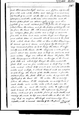
and three quarters high and one and fifteen sixteenths of an inch wide at the bottom and tapering to one and seven sixteenths of an inch at the top, and are the same distance apart from each other as the sides above described and the centers of these posts are about eight inches and three eighths of an inch distant from the sides. B, B, designates what I term the cleaver and for the purpose of taking the cotton from the band H. It is made of hard wood and is an octagon from four inches and a half in diameter from side to side and nine inches long) and has guide-ears which turn in movable slits screwed to the posts B, B, which slits have slots in them so that they may be moved up and down and fixed by the screws at any convenient place so as to bring the cleaver E' sufficiently near to the band. H, G, designates a roller of hard wood about two inches and a half in diameter and nine inches long, over which the band H passes. This roller has guide-ears which turn on bearings in the heads of the bolts C, C, which pass through the upper ends of the posts B, B, and are four inches and a half long on the outer ends of which bolts screws are cut for about two inches and a half, to which threads nuts are adapted so as to bring the heads of the bolts nearer or further distant from the posts B, B, in order to regulate the tightness of the band H. The roller G is directly above the cleaver E, H, designates an endless band of neat leather nine inches wide which passes over the steel roller A, and the wooden roller G sufficiently tight to cause it to revolve. It is formed by passing down each end of a suitable piece of neat leather and causing the ends to lap over each other so that the band may be of an uniform thickness and connecting them together with a cement made of the Russian Glycerine.
Page 5.
266.
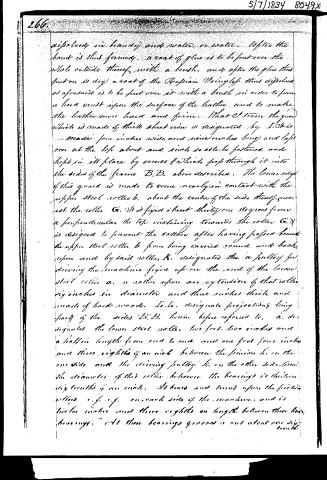
dissolved in brandy and water, or water. After the hands is thus formed, a coat of glue is to be put over the whole outside thereof, with a brush, and after the glue thus put on is dry, a coat of the Russian Varnish thus dissolved as aforesaid is to be put over it with a brush in order to form a hard crust upon the surface of the leather and to make the leather more hard and firm. That I term the guard which is made of thick sheet iron is designated by I. It is made four inches wide and nine inches long and laps over at the top about and inch so as to be fastened and kept in its place by screws & which pass through it into the sides of the frame B.B. above described. The lower edge of this guard is made to come nearly in contact with the upper steel roller b, about the centre of the side thereof nearest the roller G. It is fixed about thirty-one degrees from a perpendicular the top inclining towards the roller G. It is designed to prevent the cotton after having passed beneath the upper steel roller b from being carried round and back upon and by said roller, b. designates the a pulley for driving the machine fixed upon the end of the lower steel roller a, or rather upon an extension of that roller six inches in diameter and three inches thick, and made of hard wood. L.L. designate projections being parts of the sides B.B. herein before referred to, a. designates the lower steel roller two feet two inches and a half in length from end to end and one foot four inches and three eighths of an inch between the pinion b, on the one side and the driving pulley b, on the other side. The diameter of this roller between the bearings is thirteen and a half inches. It turns and turns upon the friction rollers c, c, c, on each side of the machine, and is twelve inches and three eighths in length between these bearings. At these bearings gears are set about one inch
Page 6.
5/7/1834 8049x
5
267
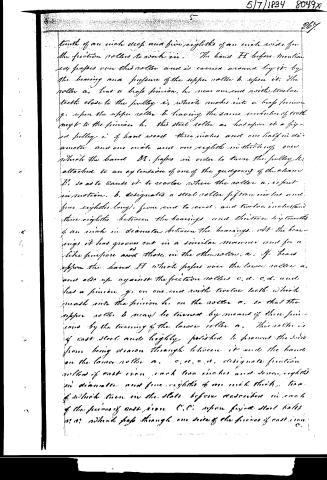
teeth of an inch deep and five eighths of an inch wide for the friction rollers to work in. The band H before mentioned passes over this roller and is carried around by it by the bearing and pressure of the upper roller b. upon it. The roller a, has a half pinion, h, near one end with twelve teeth close to the pulley i, which makes into a half pinion g, upon the upper roller b, having the same number of teeth next to the pinion h. This steel roller as has upon it a fixed pulley i, of hard wood three inches and one half in diameter and one inch and one eighth in thickness over which the band H, passes in order to turn the pulley h, attached to an extension of one of the guides of the chain H, so as to cause it to rotate when the roller a, is put in motion. b, designated a steel roller fifteen inches and five eighths long, from end to end, and twelve inches and three eighths between the bearings and thirteen sixteenths of an inch in diameter between the bearings. At the bearings it has grooves cut in a similar manner and for a like purpose as those in the other roller, a. If bands upon the band H which passes over the lower roller a, and also up against the friction rollers c, d, c, d, and has a pinion g, on one end with twelve teeth which mesh into the pinion h, on the roller a, so that the upper roller b may be turned by means of these pinions by the turning of the lower roller a. This roller is of cast steel and highly polished to prevent the sand from being drawn through between it and the band on the lower roller a. c, c, c, c, designate friction rollers of cast iron, each two inches and seven eighths in diameter and five eighths of an inch thick, two of which turn in the slots before described in each of the frames of cast iron C, C, upon fixed steel balls or on wheels pass through one side of the frames of cast iron C.
Page 7.
C, and are screwed in to the other by means of a screw cut at the end of the bolts. These rollers bear upon the upper steel roller, b, when grooves are cut as before mentioned to prevent the roller from sliding from its place. c, f, c, f, designate similar cast iron friction rollers of similar dimensions, two of which turn in each of the slots before described in the pieces of cast iron D. D, upon similar bolts r, r, upon which friction rollers the under steel roller, a, bears at the grooves cut in it for a like purpose as those cut in the upper rollers, g, and h, on the pivots before referred to and described. i, designates the pulley before described for communicating the motion of the roller a, to the cleaver I; h, designates the pulley before referred to attached to the extension of one of the gudgeons of the cleaver I. This pulley is of hard wood six inches and a half in diameter and one inch and one eighth thick, and it is fastened on the end of the extended gudgeon by means of a screw and nut. L, designates the extension of the gudgeon before mentioned, made of wrought iron. m, m, designate male screws five inches long and about three eighths of an inch in diameter which at the lower end are screwed into the projections m, m, being parts of the sides 13, 13, before referred to, the upper ends of which screw pass through the pieces of cast iron C, C, before referred to so that by means of thumb nuts screwed upon the upper end of these screws the pieces of cast iron C, C, may be screwed down so as to regulate the bearing and pressure of the friction rollers c, d, e, etc., upon the upper steel b. n, n, designate the projections being part of the sides 13, 13, for retaining the ends of the screws m, m, before mentioned. O, O, designate the bolts before referred to and described. p, p, designate the projections before
Page 8.
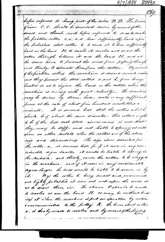
before referred to being part of the sides B, B. The pieces of iron C, C, should be screwed down by means of the screws and thumb nuts before referred to so as to make the friction rollers c, d, c, d, bear sufficiently hard upon the polished steel rollers b, to cause it to bear sufficiently hard on the band H, to make it revolve and draw the cotton through between it and the band H, and at the same time to prevent the seeds from passing through and thereby to separate them from the cotton. By means of the friction rollers the machine is moved much easier and they prevent the steel rollers a, and b, from being heated so as to injure the band or the cotton when the machine is moving with great velocity. The machine may be driven by steam, horse, water or any sufficient power at the rate of about five hundred revolutions a minute. It is deemed best that the rollers a, and b, should be of about the same diameter. These rollers ought to be of the best cast steel in order that they may be stiff and not liable to spring as will iron or other metals when the rollers are of the above size and dimensions. The size above described for the roller, a, is deemed best, for if it were in any considerable degree smaller it would be liable to spring in the middle, and thereby cause the cotton to be clogged in the machine, and if it were in any considerable degree larger the seeds would be liable to be drawn in by it. By the roller b, being small and unvarnished and highly polished it does not act upon the seeds so as to wear them in. The stone b' should be made to revolve as near the band H, as may be without touching it when the machine is put in operation, by motion communicated to the pulley K, the lower steel roller a, is thereby made to revolve and by means of the spring
Page 9.
270.
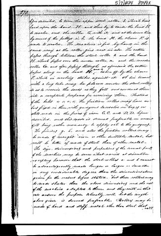
Before described, to turn the upper steel roller b, which bears hard upon the band II, and thus by to cause the band II to revolve and the roller C, with it, and at the same time by means of the pulleys i, k, the board M, the cleaver l', is made to revolve. The machine is fed by hand in the same way as the roller gin now in use. The cotton passes through between the steel roller b, and the band II, which passes over the under roller a, and the wooden roller C, and after passing through as aforesaid the cotton passes along on the band II, and is taken off by the cleaver l', which in revolving strikes against it. A tin funnel with a long tube may be placed under the steel roller so as to receive the seeds as they fall and conduct them into a receptacle prepared for receiving them. Instead of the bolts v, v, v, v, the friction rollers may have axles fixed in them with guageons to revolve in boxes or slots made in the pieces of iron C, C, and D, D, before described, and this mode is deemed preferable on account of its being rather more easy to apply oil to the guageons. The pinions g, h, and also the friction rollers may be made of wrought iron or other suitable metal, but will be better if made of steel than of other metal. The size, dimensions and proportions of the several parts of the machine may be somewhat varied at discretion excepting however that the steel rollers a and b cannot be advantageously made longer or larger or smaller in any considerable degree than the dimensions above given for the reasons before stated, but these rollers may be made shorter than the above dimensions and the rest of the machine adapted to them and they will in this case answer the purpose tolerably well, but the length above given is deemed preferable. Rollers may be made of hard and stiff metal other than steel that will
Page 10.
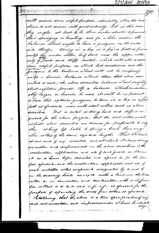
will answer some useful purpose, especially, when the machine is not driven with great velocity, but in this case they ought at least to be three inches shorter to prevent their springing or breaking, and for a like reason the balance wheel ought to have a guigeon on the outer side thereof, turning in a box in a fixed part or frame unless the under roller be of steel and the upper roller only of hard and stiff metal, which will also answer some useful purpose, in which last mentioned case the guigeon to the balance wheel will not be necessary unless a heavier balance wheel than that above described is used; the above described balance wheel weighing about eighteen pounds. If a balance wheel considerably larger or heavier be used it will be expedient to have this exterior guigeon to turn in a box in a fixed part as aforesaid, even with steel rollers such as above described. But a metal so strong, hard and stiff is required for the above purpose, that the steel rollers such as first above described we deemed far preferable to any other, as being less liable to spring or break than any other rollers of the same size and length. What I claim as new and of my invention and all which I claim as my invention and improvement in the above machine is the construction, application and use of such guards, as I term it as is herein before described and referred to, for the purpose aforesaid, and the construction, application and use of such metallic rollers as aforesaid designated by a, and b, in the drawing hereto annexed with a band over the lower roller as, in combination and combination with such friction rollers c, d, e, f, and g, as aforesaid for the purpose of separating the seeds from cotton as aforesaid.
Witness that the above is a true specification of my said invention and improvement I have hereunto set my
Page 11.
272.
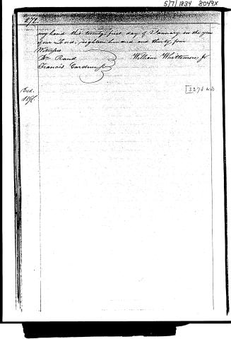
my hand this twenty-first day of January in the year
of our Lord, eighteen hundred and thirty-four
Witnesses
Dr. Rand
Francis Gardiner Jr
William Whittemore Jr
3278 w.3
Exd.
1196.
Published accounts: journal notice
Notice in the monthly list of patents, with remarks
Journal of the Franklin Institute, new ser., vol. 14 (1834), p. 236 · View the page
14. For an improvement in the Roller Gin for Separating the Seeds from Cotton; William Whittemore, jr. West Cambridge, Middlesex county, Massachusetts, March 7.
Remarks. The specification of this patent is one of considerable length, and refers throughout to the drawings. As the machine is one in which but few of our readers will feel an interest, we shall not attempt to epitomise the description, nor shall we give the claim, as this, without the drawings, would afford but little insight into the matter.
About this record
- Patentee
- DATAMP
- Date
- the Name and Date index of patents, DATAMP, USPTO records
- Invention
- DATAMP
- Listed in
- the Name and Date index of patents, DATAMP, USPTO records, Jim Shaw's X-patent list, the Journal of the Franklin Institute, Burke's List of Patents (1847)
- Burke's 1847 Patent Office list gives the same patent.